Electromagnetic tooth embedding type clutch and two-motor hybrid power system

A clutch and cogging technology, applied in the direction of power devices, electric components, pneumatic power devices, etc., can solve the problems of limited torque capacity, large space occupation, heavy weight, etc., and achieve large transmission torque, rapid action, and compact structure Effect

Active Publication Date: 2014-12-10
JING JIN ELECTRIC TECHNOLOGIES (BEIJING) CO LTD
View PDF4 Cites 10 Cited by
  • Summary
  • Abstract
  • Description
  • Claims
  • Application Information

AI Technical Summary

Problems solved by technology

The existing clutches used in dual-motor hybrid hybrid systems directly follow the dry clutches in traditional automobiles, but dry clutches are limited by their structure, occupying a large space and weight, and have a large torque capacity. The disadvantages of limited and external actuator drive that require a large thrust limit the further improvement of the performance of the dual-motor hybrid hybrid system of the car, and become the bottleneck of the development of the dual-motor hybrid hybrid system.

Method used


Image

  • Electromagnetic tooth embedding type clutch and two-motor hybrid power system
  • Electromagnetic tooth embedding type clutch and two-motor hybrid power system
  • Electromagnetic tooth embedding type clutch and two-motor hybrid power system

Examples


Embodiment 1

[0045] Embodiment 1 Electromagnetic tooth clutch

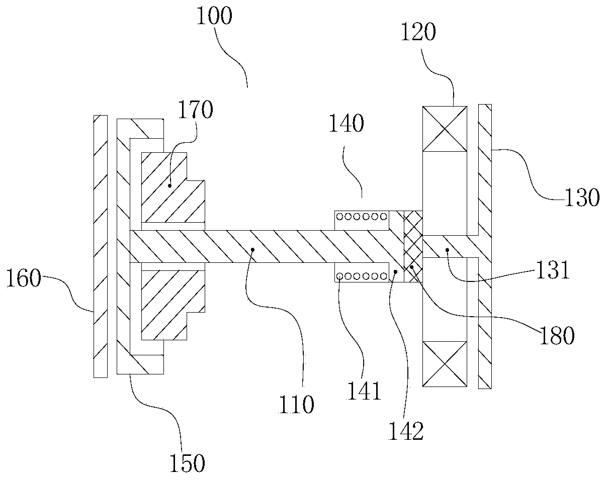
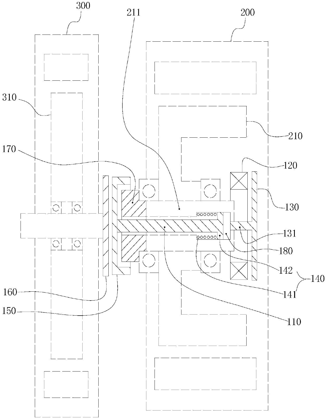
[0046] see figure 1 and figure 2 , this embodiment discloses an electromagnetic tooth clutch 100, which is used to realize the driving clutch of the first motor 300 and the second motor 200, the clutch includes a joystick 110, a ring electromagnet 120, an armature 130 and an elastic reset mechanism 140 , and includes a matching movable face gear 150 and a fixed face gear 160 . In order to show the positional relationship of each member of the clutch of the present invention more clearly, to show the difference in structure and effect between it and the existing clutch, figure 2 The first motor 300 and the second motor 200 are shown in dashed lines, the first motor 300 includes the rotor 310 of the first motor, the second motor 200 includes the rotor 210 of the second motor, and the rotor 210 of the second motor includes Shaft 211. In the following description of this embodiment, the structural relationship between the co...

Embodiment 2

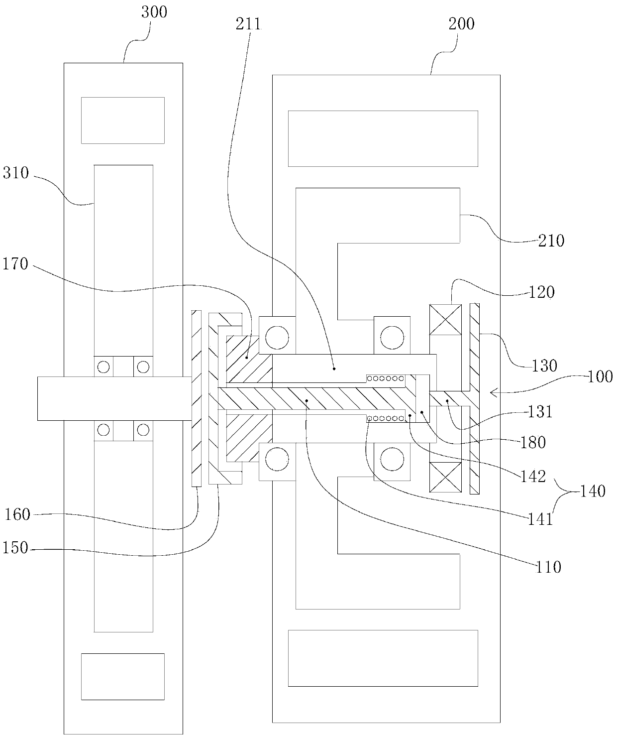
[0055] Embodiment 2 Dual-motor hybrid power system

[0056] see image 3 , the present invention provides a dual-motor hybrid power system, the system includes a first motor 300 and a second motor 200, and includes the electromagnetic dog clutch 100 of Embodiment 1, and the technical solution described in Embodiment 1 also belongs to this Embodiment, Embodiment 1 The scheme that has been described will not be described again.

[0057] The electromagnetic dog clutch 100 is disposed between the first motor 300 and the second motor 200 , and is used to realize the drive clutch of the first motor 300 and the second motor 200 .

[0058] It can be seen from the description of the first embodiment that the joystick 110 and the elastic return mechanism 140 are located in the inner cavity of the rotor 210 of the second motor, and the armature 130 and the ring electromagnet 120 are located in the second motor The outer side of the rotor 210, that is, away from the first motor 300; the...

Embodiment 3

[0059] Embodiment 3 Dual-motor hybrid power system

[0060] see Figure 4 and Figure 5 , this embodiment also provides a dual-motor hybrid system, which is a further improvement on the basis of Embodiment 2. The technical solution disclosed in Embodiment 2 also belongs to this embodiment. The technology described in Embodiment 2 The scheme will not be described repeatedly. Figure 4 In , the solid line represents the transmission of mechanical force, and the dashed line represents the transmission of electric power.

[0061]Specifically, on the basis of the technical solution described in the second embodiment, that is, on the basis that the second motor 200 realizes the driving and clutching of the first motor 300 through the electromagnetic dog clutch 100, the The dual-motor hybrid system further includes an engine 400 , a first motor driver 500 , a second motor driver 600 and an energy storage device 700 . The engine 400 is coupled to the first electric motor 300 by me...


PUM


Abstract

The invention discloses an electromagnetic tooth embedding type clutch used for achieving driving separation and reunion of a first motor and a second motor. The clutch comprises a joystick, an annular electromagnet, an armature, an elastic reset mechanism, a movable end face gear and a fixed end face gear, wherein the joystick is inserted in an inner cavity of a rotor of the second motor, the two ends of the joystick are located on the two sides of the rotor of the second motor respectively, a magnetic attraction mechanism and a mesh transmission mechanism are located on the end sides of the rotor of the second motor respectively, compact axial arrangement is achieved, and therefore space of the clutch is substantially saved, and structural compactness degree of the clutch is improved. The invention further discloses a two-motor hybrid power system, under the action of the structural characteristics of the electromagnetic tooth embedding type clutch, an engine, the first motor and the second motor can be coaxially arranged, and according to the arrangement mode, not only is the advantage that the structure is compact achieved, but also transmission efficiency is improved.

Description

technical field [0001] The invention relates to the technical field of automobile hybrid power, in particular to an electromagnetic tooth clutch and a dual-motor hybrid power system using the clutch. Background technique [0002] In the field of automotive hybrid power, most of them adopt a dual-motor hybrid system, which is formed by the linkage of the first motor and the second motor. A clutch is provided between the first motor and the second motor, and the switching of the pure electric, series or parallel driving modes of the dual-motor hybrid system is realized through the clutch state of the clutch. [0003] At present, there is no special clutch used between the first motor and the second motor in this field. The existing clutches used in dual-motor hybrid hybrid systems directly follow the dry clutches in traditional automobiles, but dry clutches are limited by their structure, occupying a large space and weight, and have a large torque capacity. The above shortco...

Claims


Application Information

Patent Timeline
Patent Type & Authority Applications(China)
IPC IPC(8): B60K6/38H02K7/10B60K6/50
Inventor 余平叶晓王婷王学良
Owner JING JIN ELECTRIC TECHNOLOGIES (BEIJING) CO LTD
Why Eureka
Try Eureka