
Emulsion wastewater treatment process and device

A technology for wastewater treatment and emulsification, which is applied in water/sewage multi-stage treatment, water/sludge/sewage treatment, chemical instruments and methods, etc. Improve stability and life, low comprehensive treatment cost, and improve the effect of effluent quality

Inactive Publication Date: 2014-12-10
无锡格物环保技术有限公司
View PDF3 Cites 12 Cited by
  • Summary
  • Abstract
  • Description
  • Claims
  • Application Information

AI Technical Summary

Problems solved by technology

However, the current chemical or ionization demulsification devices and methods have the following defects: using chemical demulsification requires different demulsifiers according to different emulsion systems, and the amount of demulsifier is large, and the overall input cost is high; ionization demulsification It can only be used for water-in-oil emulsion wastewater, and the effect is very poor for other types of emulsion wastewater
However, the membrane method currently uses organic membranes and ceramic membranes to treat emulsions. Due to their special structure, ceramic membranes solve the problems of high temperature resistance and acid resistance, but ceramic membranes are easily broken, with small channels, low concentration ratios, and unstable operation. , is difficult to clean, cannot resist sudden cooling and sudden heat, and has high requirements for operation and automation
In order to solve the above problems, organic membranes have been applied to emulsion treatment. Generally, organic membranes have poor pollution resistance, low concentration multiples, high temperature resistance, acid and alkali resistance, and high frequency of membrane replacement.

Method used


Image

  • Emulsion wastewater treatment process and device
  • Emulsion wastewater treatment process and device

Examples


Embodiment Construction

[0017] In order to make the object, technical solution and advantages of the present invention clearer, the present invention will be further described in detail below in conjunction with the accompanying drawings and embodiments. It should be understood that the specific embodiments described here are only used to explain the present invention, not to limit the present invention.

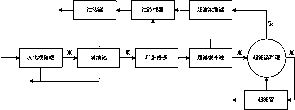
[0018] Such as figure 1 As shown, the oily emulsion wastewater in industrial production is discharged into the emulsion storage tank through pipelines, and then pumped into the grease trap. A steam heater is installed in the pool to heat the oily wastewater to reduce the viscosity of the oily wastewater and make the sewage better. static separation. After static separation, the oily wastewater in the pool is divided into three layers, the surface layer is oil slick, the middle layer is emulsion, and the bottom layer is oily sludge containing impurities. The oil sludge at the bottom of the emulsio...


PUM


Abstract

The invention relates to an emulsion wastewater treatment process and device. The treatment process comprises the steps that the wastewater is pumped into an oil separator from an emulsion storage tank and floating oil is collected in an oil concentrator; the emulsion enters a drum grille to further remove small particle impurities likely to scratch an ultrafiltration membrane; an ultrafiltration buffer pool is used for receiving the oily wastewater and the oily wastewater is used for buffering ultrafiltration water inflow, wherein the floating oil enters the oil concentrator; the remaining wastewater is pumped into an ultrafiltration circulation tank and then is treated with the ultrafiltration membrane, and the emulsion is broken here; the ultrafiltered water is discharged to a subsequent biotreatment system; the floating oil and the oil after ultrafiltration and emulsion breaking enter the oil concentrator and self-flow into an oil storage tank after being further concentrated. The process and the device have the beneficial effects that any chemical agent is not used; the emulsion is broken by adopting a membrane treatment method, thus avoiding secondary pollution; the imported ultrafiltration membrane is adopted, so that the ultrafiltration effect is good and blockage is not easy to happen.

Description

technical field [0001] The invention relates to an oil-containing emulsion wastewater treatment process and a device, in particular to an oil-containing emulsion wastewater treatment process and a device for realizing demulsification by an ultrafiltration method. Background technique [0002] Emulsified oily wastewater and waste emulsion are the most difficult types of oily wastewater to treat. Because the emulsion contains a certain amount of surfactant, the combination of oil molecules and water molecules is particularly firm. At present, the demulsification treatment methods for oil-containing emulsion wastewater include heating, ionization, chemical, physical and other methods, among which the chemical or ionization demulsification method is the most widely used, and its demulsification effect is also relatively ideal. However, the current chemical or ionization demulsification devices and methods have the following defects: using chemical demulsification requires differ...

Claims


Application Information

Patent Timeline
IPC IPC(8): C02F9/02
Inventor 戴朝杰
Owner 无锡格物环保技术有限公司
Learn More