
A test bench for oil injection pump and cooling pump

A technology for oil return pump and cooling pump, which is used in pump testing, liquid variable capacity machinery, machines/engines, etc. It can solve the problems of high price, high noise, complicated operation, etc., and achieve strong corrosion resistance and stable performance. , measure the precise effect

Active Publication Date: 2016-05-18
南京创贝高速传动机械有限公司
View PDF7 Cites 0 Cited by
  • Summary
  • Abstract
  • Description
  • Claims
  • Application Information

AI Technical Summary

Problems solved by technology

[0002] Injection, oil return pump and cooling pump are auxiliary oil supply, oil return, and cooling systems inside the product. On the one hand, the oil injection pump provides the required hydraulic energy for the product, and at the same time provides the lubricating oil required for lubrication and cooling; on the other hand In order to prevent the abnormal heating caused by the internal rotating parts of the product being in the lubricating oil and the scouring damage of the high-speed rotating parts, the oil return pump at the bottom of the product draws back the lubricating oil inside the shell and dissipates heat through the external radiator of the product. Guarantee the normal operation of the product; its performance directly affects the normal operation of the electrical system, the service life of electrical equipment, and even production efficiency; when the injection, oil return pump and cooling pump are in use, when the technical parameters change or are repaired After that, it must be checked and adjusted on the test bench to restore the original technical state. Therefore, the inspection and adjustment of the injection, oil return pump and cooling pump is an important common technology in production; most of the injection, oil return pumps and cooling pumps on the market The cooling pump test bench relies on imports, or the production cost is high, expensive, and the operation is complicated, difficult to master, and the working noise is loud, which is not conducive to the health of the staff. At present, it can no longer satisfy people's high precision, large range, corrosion resistance , explosion-proof and other performance requirements

Method used


Image

  • A test bench for oil injection pump and cooling pump

Examples


Embodiment 1

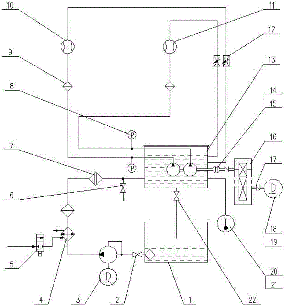
[0016] This embodiment provides a test bench for oil injection and return pumps and cooling pumps, the structure of which is as follows: figure 1 As shown, it includes lower oil tank 1, working oil tank 13, magnetoelectric speed sensor 14, speed increasing box 16, coupling 17, frequency conversion speed regulating motor 18, temperature sensor 20 and oil discharge switch 22, and lower oil tank 1 is located at working oil tank 13 The bottom is connected to the working oil tank 13, the oil drain switch 22 is connected to the bottom of the working oil tank 13 and the outlet faces the lower oil tank 1, the temperature sensor 20 is connected to the side wall of the working oil tank 13, the frequency conversion motor 18 is connected to the input end of the coupling 17, and the coupling The output end of 17 is connected to the input end of speed-up box 16, and the output end of speed-up box 16 is connected to magnetoelectric speed sensor 14 through coupling, and magnetoelectric speed s...


PUM


Abstract

The invention discloses a test bench for an oil injection pump and a cooling pump, which comprises a stainless steel ball valve, a vane type oil pump, a stainless steel cooler, a two-position two-way electromagnetic water valve, an air-conditioning switch, a first hydraulic oil filter, a pressure sensor, a second hydraulic Oil filter, turbine flow meter and pressure regulating switch. An oil outlet pipeline is set under the lower oil tank, and the oil outlet pipeline is connected to the working oil tank. A stainless steel ball valve is installed at the outlet of the oil outlet pipeline. The input end of the stainless steel cooler is connected to the two-position two-way electromagnetic water valve, and the end of the oil outlet pipeline close to the working oil tank is provided with a bypass, the bypass is equipped with a cold air switch, and the working oil tank is equipped with a cooling pump Test circuit and oil return pump test circuit; according to the test requirements of product components, the present invention verifies whether the performance of the oil injection and return pump meets the requirements through the measured parameters of the test. This product has accurate measurement, low cost, low noise, safety and environmental protection, and stable performance .

Description

technical field [0001] The invention belongs to the field of experimental equipment, and relates to a test bench, in particular to a test bench for an oil injection pump and a cooling pump. Background technique [0002] Injection, oil return pump and cooling pump are auxiliary oil supply, oil return, and cooling systems inside the product. On the one hand, the oil injection pump provides the required hydraulic energy for the product, and at the same time provides the lubricating oil required for lubrication and cooling; on the other hand In order to prevent the abnormal heating caused by the internal rotating parts of the product being in the lubricating oil and the scouring damage of the high-speed rotating parts, the oil return pump at the bottom of the product draws back the lubricating oil inside the shell and dissipates heat through the external radiator of the product. Guarantee the normal operation of the product; its performance directly affects the normal operation ...

Claims


Application Information

Patent Timeline
Patent Type & Authority Patents(China)
IPC IPC(8): F04B51/00
Inventor 陆树根杨忠喜冯强龙
Owner 南京创贝高速传动机械有限公司
Learn More