
Delay chain temperature drift on-orbit correction device and method based on FPGA

A temperature drift and delay chain technology, applied in temperature control, non-electric variable control, instruments, etc., can solve the problems of poor accuracy, no correction of temperature drift, and reduced degree of conformity of temperature change curves, and achieves the use of The effect of flexibility, low power consumption, and low resource consumption

Inactive Publication Date: 2014-12-10
SHANGHAI ENG CENT FOR MICROSATELLITES
View PDF7 Cites 12 Cited by
  • Summary
  • Abstract
  • Description
  • Claims
  • Application Information

AI Technical Summary

Problems solved by technology

However, the patent proposes to use a linear function to fit the temperature drift of the delay unit, which can only be applied to a small operating temperature range
When the temperature change range is large, the conformity of the linear function to the temperature change curve will be reduced, and the accuracy of the linear function method will be correspondingly reduced.
At the same time, the patent describes the process of offline correction of temperature drift, but does not provide a method for real-time correction of temperature drift in FPGA, and its application in the space environment has certain limitations.

Method used


Image

  • Delay chain temperature drift on-orbit correction device and method based on FPGA
  • Delay chain temperature drift on-orbit correction device and method based on FPGA
  • Delay chain temperature drift on-orbit correction device and method based on FPGA

Examples


Embodiment Construction

[0027] The specific implementation of the FPGA-based on-orbit correction device and method for temperature drift of the delay chain provided by the present invention will be described in detail below with reference to the accompanying drawings.

[0028] Firstly, the embodiment of the FPGA-based on-orbit correction device for delay chain temperature drift of the present invention is given in conjunction with the accompanying drawings.

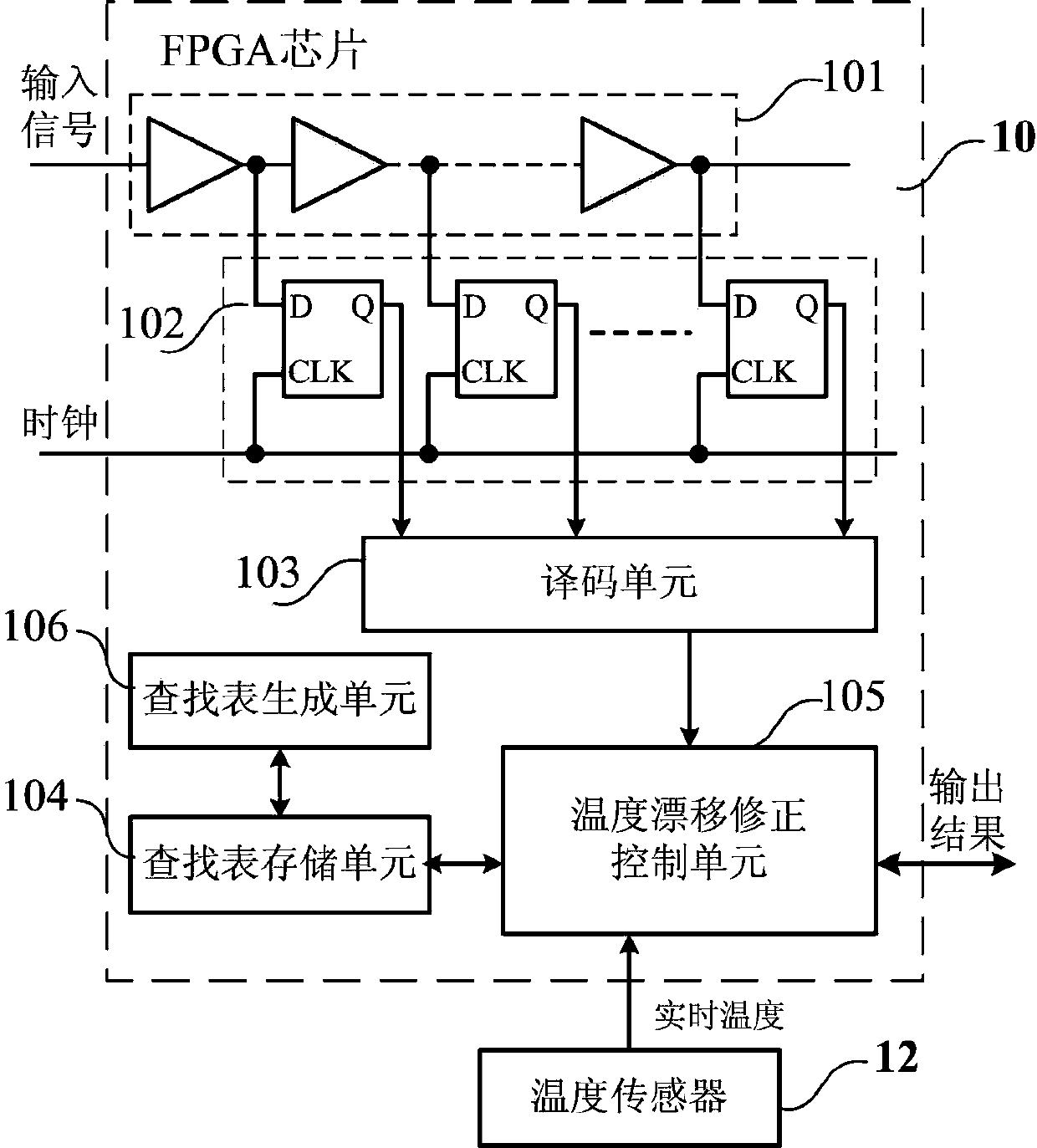
[0029] see figure 1 , the structure diagram of the on-orbit correction device for delay chain temperature drift based on FPGA according to the present invention. The correction device includes a temperature sensor 12 , a delay chain 101 , a D flip-flop array 102 , a decoding unit 103 , a lookup table storage unit 104 and a temperature drift correction control unit 105 . The delay chain 101, the D flip-flop array 102, the decoding unit 103, the look-up table storage unit 104 and the temperature drift correction control unit 105 are integrated in...


PUM


Abstract

The invention discloses a delay chain temperature drift on-orbit correction device and a delay chain temperature drift on-orbit correction method based on FPGA. The device comprises a temperature sensor, a delay chain, a D trigger array, a decoding unit, a lookup table storage unit and a temperature drift correction control unit, wherein the temperature sensor is used for collecting real-time temperature; the delay chain is used for reading out time information of an input signal relating to a clock edge; the D trigger array is connected to the delay chain, for locking an output state of each delay unit in the delay chain when arriving the clock edge and outputting temperature coding data; the decoding unit is connected to the D trigger array, for converting the temperature coding data into binary code data and outputting; the lookup table storage unit is used for storing integral nonlinear lookup table data of the delay chain marked at a preset temperature point; the temperature drift correction control unit is connected to the temperature sensor, the decoding unit and the lookup table storage unit respectively, for achieving on-orbit correction of delay chain temperature drift. According to the delay chain temperature drift on-orbit correction device and method based on FPGA, correction of the delay chain temperature drift is achieved by fewer sources, and high time resolution capacity is ensured.

Description

technical field [0001] The invention relates to the fields of aerospace and semiconductor technologies, in particular to an FPGA-based on-orbit correction device and method for temperature drift of a delay chain. Background technique [0002] With the rapid development of aerospace and semiconductor technology in recent years, more and more semiconductor integrated devices have been applied in space missions. In many space applications, high-precision time-resolution capabilities of semiconductor devices are required, such as satellite altimeters, space range finders, space telemetry, time calibration, time calibration in space quantum communications, space high-energy particle spectrometers and plasma Time-of-flight measurement systems for spectrometers, and a series of high-precision time-measurement measurement systems. Usually, a semiconductor device can use multiple delay units to be cascaded to realize the interpolation of the main clock cycle of the device to achieve...

Claims


Application Information

Patent Timeline
Patent Type & Authority Applications(China)
IPC IPC(8): G05D23/20
Inventor 秦熙吴树范陈雯陈雯雯
Owner SHANGHAI ENG CENT FOR MICROSATELLITES
Learn More