A device and method for monitoring link failures of time-division multiplexed optical networks

A technology of network link and multiplexing light, applied in electromagnetic wave transmission systems, electrical components, transmission systems, etc., can solve the problems of low spatial resolution, small dynamic range, complex structure, etc., and achieve low spatial resolution and sensitivity. Improve and simplify the effect of the structure

Active Publication Date: 2016-06-29
TAIYUAN UNIV OF TECH
View PDF7 Cites 0 Cited by
  • Summary
  • Abstract
  • Description
  • Claims
  • Application Information

AI Technical Summary

Problems solved by technology

[0014] In order to solve the problems of low spatial resolution, complex structure, low sensitivity and small dynamic range of the existing time-division multiplexing passive optical network fault monitoring technology, the present invention provides a device and method for monitoring time-division multiplexing optical network link faults

Method used


Image

  • A device and method for monitoring link failures of time-division multiplexed optical networks
  • A device and method for monitoring link failures of time-division multiplexed optical networks
  • A device and method for monitoring link failures of time-division multiplexed optical networks

Examples


Embodiment 1

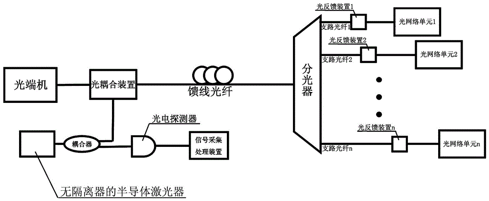
[0045] A device for monitoring link failures of a time-division multiplexing optical network, including a time-division multiplexing optical network and a monitoring device;

[0046] The time-division multiplexing optical network includes an optical terminal, a feeder optical fiber, an optical splitter of n channels, n branch optical fibers, and n optical network units; the optical terminal is connected to the common port of the optical splitter through the feeder optical fiber; the n optical splitters The splitting port is connected one by one to the incident end faces of n optical network units through n branch optical fibers;

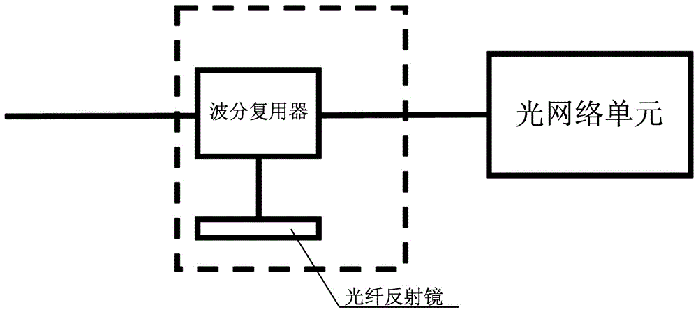
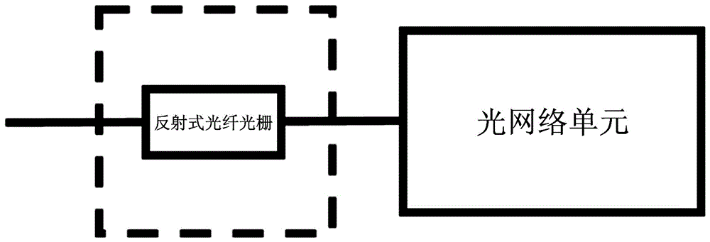
[0047] The monitoring device includes a semiconductor laser without an isolator, a coupler, an optical coupling device, a photodetector, a signal acquisition and processing device, and n optical feedback devices; the semiconductor laser without an isolator is connected to the coupler; the large ratio of the coupler The output end is connected to the ...

Embodiment 2

[0058] A device for monitoring link failures of a time-division multiplexing optical network, including a time-division multiplexing optical network and a monitoring device;

[0059] The time-division multiplexing optical network includes an optical terminal, a feeder optical fiber, an optical splitter of n channels, n branch optical fibers, and n optical network units; the optical terminal is connected to the common port of the optical splitter through the feeder optical fiber; the n optical splitters The splitting port is connected to the incident end faces of n optical network units through n branch optical fibers in one-to-one correspondence;

[0060]The monitoring device includes a semiconductor laser without an isolator, a coupler, an optical coupling device, a photodetector, a signal acquisition and processing device, and n optical feedback devices; the semiconductor laser without an isolator is connected to the coupler; the large ratio of the coupler The output end is ...

Embodiment 3

[0071] A device for monitoring link failures of a time-division multiplexing optical network, including a time-division multiplexing optical network and a monitoring device;

[0072] The time-division multiplexing optical network includes an optical terminal, a feeder optical fiber, an optical splitter of n channels, n branch optical fibers, and n optical network units; the optical terminal is connected to the common port of the optical splitter through the feeder optical fiber; the n optical splitters The splitting port is connected one by one to the incident end faces of n optical network units through n branch optical fibers;

[0073] The monitoring device includes a semiconductor laser without an isolator, a coupler, an optical coupling device, a photodetector, a signal acquisition and processing device, and n optical feedback devices; the semiconductor laser without an isolator is connected to the coupler; the large ratio of the coupler The output end is connected to the ...


PUM


Abstract

The invention relates to an optical fiber communication network fault monitoring technology, in particular to a device and method for monitoring a time division multiplexing optical network link fault. The invention solves the problems of low spatial resolution, complex structure, low sensitivity and small dynamic range of the existing time-division multiplexing passive optical network fault monitoring technology. A device for monitoring link failures in a time-division multiplexing optical network, including a time-division multiplexing optical network and a monitoring device; the time-division multiplexing optical network includes an optical terminal, a feeder optical fiber, an optical splitter for 1 point and n paths, and n branch optical fibers , n optical network units; the monitoring device includes a semiconductor laser without an isolator, a coupler, an optical coupling device, a photodetector, a signal acquisition and processing device, and n optical feedback devices; a semiconductor laser without an isolator and a coupler Connection; the large-scale output of the coupler is connected to the input of the optocoupler. The invention is suitable for time division multiplexing passive optical network fault monitoring.

Description

technical field [0001] The invention relates to an optical fiber communication network fault monitoring technology, in particular to a device and method for monitoring a time division multiplexing optical network link fault. Background technique [0002] At present, the optical fiber communication network has rapidly developed from the intercity backbone network to the household optical fiber access network. In various home optical fiber access networks, passive optical network (PON, Passive Optical Network) which combines wavelength division multiplexing (WDM, Wavelength Division Multiplexing) and time division multiplexing (TDM, TimeDivision Multiplexing) technology is the key to realize high-speed and large-capacity communication. The best access plan. Therefore, timely and accurate diagnosis of PON faults is of great significance to guarantee communication and digital services. Optical Time Domain Reflectometry (OTDR, Optical Time Domain Reflectometry) is currently the...

Claims


Application Information

Patent Timeline
Patent Type & Authority Patents(China)
IPC IPC(8): H04B10/071
Inventor 王安帮赵彤张明江王冰洁王云才
Owner TAIYUAN UNIV OF TECH
Why Eureka
Try Eureka