
Plated member, plated terminal for connectors, method for producing plated member, and method for producing plated terminal for connectors

一种制造方法、连接器的技术,应用在接触件制造、化学仪器和方法、接触部件等方向,能够解决端子插入力增大、摩擦系数上升、晶粒易粗大等问题,达到容易摩擦系数、摩擦系数降低、降低制造成本的效果

Inactive Publication Date: 2014-12-10
AUTONETWORKS TECH LTD +2
View PDF9 Cites 9 Cited by
  • Summary
  • Abstract
  • Description
  • Claims
  • Application Information

AI Technical Summary

Problems solved by technology

[0004] However, copper particles tend to diffuse in the silver-plated layer. Therefore, when silver-plating is performed on the surface of a terminal base material made of copper or copper alloy, there will be copper components that reach the silver-plated surface and are oxidized, resulting in increased resistance. The problem
In addition, silver has the property that crystal grains tend to be coarsened due to recrystallization, and when a silver-plated terminal is used in a high-temperature environment, the hardness decreases due to the growth of crystal grains
As a result, the insertion force of the terminal increases and the friction coefficient increases.

Method used


Image

  • Plated member, plated terminal for connectors, method for producing plated member, and method for producing plated terminal for connectors
  • Plated member, plated terminal for connectors, method for producing plated member, and method for producing plated terminal for connectors
  • Plated member, plated terminal for connectors, method for producing plated member, and method for producing plated terminal for connectors

Examples


Embodiment 1

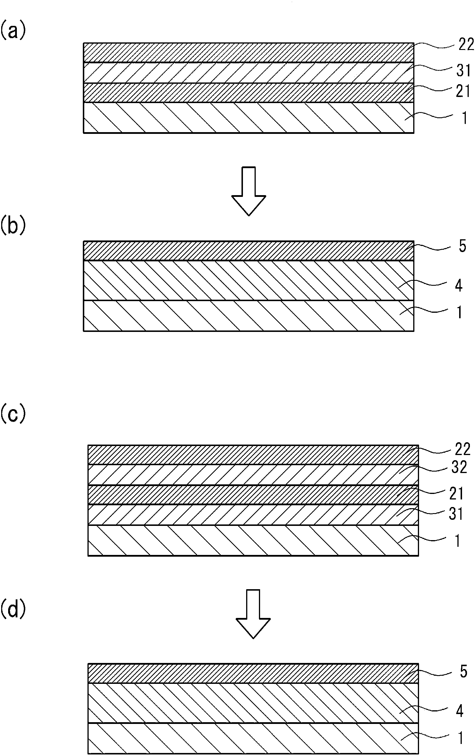
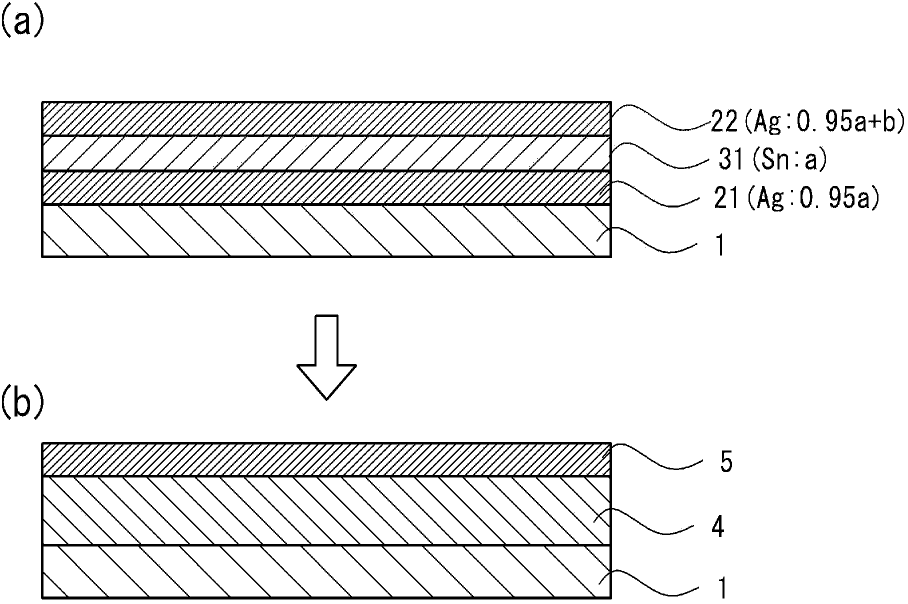
[0102] On the surface of the clean copper substrate, a nickel underplating layer with a thickness of 0.5 μm was formed. A soft silver plating layer having a target thickness of 1 μm was formed on the surface of the nickel underplating layer. A tin plating layer having a target thickness of 1 μm was formed on the soft silver plating layer, and a soft silver plating layer having a thickness of 2 μm was further formed on the tin plating layer. This material was heated at 200° C. for 60 minutes in the air. This was made into the plated part of Example 1. The specific formation conditions of the soft silver plating layer and the tin plating layer are as follows.

[0103]

[0104] Use a plating solution with an Ag concentration of 45g / L

[0105] ·Operating temperature: 30℃

[0106] ·Current density: 5ASD (2.5μm / min)

[0107] ・Plating time: 20 to 30 seconds (thickness of the plating layer: 1 μm), 40 to 60 seconds (thickness of the plating layer: 2 μm)

[0108]

[0109] Use ...

Embodiment 2

[0115] In the same manner as in Example 1, a soft silver plating layer with a target thickness of 1 μm, a tin plating layer with a thickness of 1 μm, and a soft silver plating layer with a thickness of 2 μm were sequentially laminated on the surface of a nickel-plated copper substrate in the following order. The coated parts were heated at 290°C for 1 minute.

Embodiment 3

[0117] On the surface of the nickel-plated copper substrate, a plated part in which a soft silver plating layer with a thickness of 1.5 μm, a tin layer with a thickness of 1.0 μm, and a soft silver layer with a thickness of 2.5 μm was sequentially laminated at 290 ° C Heat for 1 minute.


PUM

PropertyMeasurementUnit
particle diameteraaaaaaaaaa

Abstract

To provide, at a low cost, a plated member and a plated terminal for connectors, to each of which a large current can be applied, and each of which has a good balance between low friction coefficient and high heat resistance. To also provide a method for producing the plated member and a method for producing the plated terminal for connectors. Tin plating layers and silver plating layers are alternately laminated on the surface of a base, which is formed of copper or a copper alloy, in such a manner that a silver plating layer forms the outermost surface, and then heating is performed. Consequently, a silver-tin alloy layer that covers the surface of the base and a silver coating layer that covers the silver-tin alloy layer and is exposed as the outermost surface are formed at the same time, thereby obtaining a plated member.

Description

technical field [0001] The present invention relates to a plated part, a plated terminal for a connector, a method for manufacturing the plated part, and a method for manufacturing a plated terminal for a connector, and more specifically, to a plated part containing silver and tin in the plated layer, and a plated part for a connector. Terminals and their method of manufacture. Background technique [0002] In recent years, high-output motors are used in hybrid vehicles, electric vehicles, and the like. In the case of a terminal for a high-output motor with a large energized current, a large current flows through the connector terminal, and thus the amount of heat generated at the terminal portion increases. In addition, since the terminal becomes larger corresponding to the current capacity, the insertion force increases, and the damage to the surface of the terminal during insertion also increases. The number of plugging and unplugging of terminals due to maintenance als...

Claims


Application Information

Patent Timeline
Patent Type & Authority Applications(China)
IPC IPC(8): C25D7/00B32B15/01C25D5/10C25D5/50H01R13/03H01R43/16
CPCC25D5/50B32B15/018C23C28/023C22C5/06B32B15/01C25D7/00C25D5/10C25D5/12C25D5/611C25D5/617Y10T428/12708Y10T428/12715Y10T428/12722Y10T428/12896Y10T428/1291Y10T428/24942Y10T428/2495Y10T428/24967Y10T428/24975Y10T428/26Y10T428/263Y10T428/264Y10T428/265C23C14/16C23C14/165C23C14/58C23C14/5806C23C28/00C23C28/02C23C28/021C23C30/00C23C30/005H01R13/03H01R43/16
Inventor 须永隆弘坂喜文斋藤宁
Owner AUTONETWORKS TECH LTD
Features
  • Generate Ideas
  • Intellectual Property
  • Life Sciences
  • Materials
  • Tech Scout
  • Unparalleled Data Quality
  • Higher Quality Content
  • 60% Fewer Hallucinations
Learn More