Worm machining device

A processing device and worm technology, which is applied to worms, components with teeth, belts/chains/gears, etc., can solve problems such as low transmission efficiency of worms, difficulty in ensuring the shape and position accuracy of tooth grooves, and troublesome tooth shapes of worm gears, etc.

Active Publication Date: 2014-12-17
SHENYUE FUJIAN CASTING
View PDF6 Cites 3 Cited by
  • Summary
  • Abstract
  • Description
  • Claims
  • Application Information

AI Technical Summary

Problems solved by technology

4. The efficiency of worm transmission is low. It is generally believed that the efficiency of worm transmission is lower than that of gear transmission.
However, the shape processing and manufacturing of the worm gear tooth profile is troublesome, and it is difficult to ensure the accuracy of the processed tooth groove shape and position
[0003] In particular, in some specific application areas, such as soft materials (such as plastics) processing, traditional metal processing methods will be difficult to meet the requirements of reducing costs and improving processing speed and accuracy

Method used


Image

  • Worm machining device
  • Worm machining device

Examples


Embodiment Construction

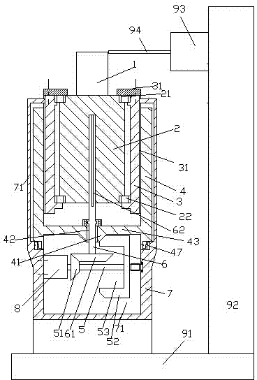
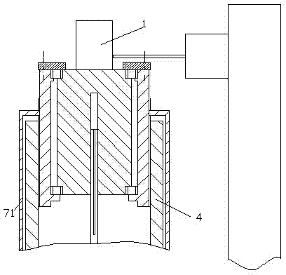
[0013] Attached below Figure 1-2 , the present invention will be described in detail.

[0014] A worm processing device, used to process the blank 1 into a worm, comprising a movement mechanism, a base 91, a column 92, a milling cutter rotation drive motor 93 and a milling cutter 94, the movement mechanism is fixed on the base 91, and the movement mechanism of the column 92 The lower end is fixedly connected with the base 91, and the milling cutter rotation drive motor 93 is installed on the upper end of the column 92 for driving the rotation of the milling cutter 94, and the milling cutter 94 is installed on the milling cutter rotation drive motor 93 for cutting the blank 1. The motion mechanism includes a blank carrier 2, a sleeve 3 with external threads, a drive sleeve 4 with internal threads, and a frame 7. The blank carrier 2 is used to carry the blank 1, and the blank The upper end and the lower end of the bearing member 2 are axially fixedly installed in the sleeve 3 ...


PUM


Abstract

The invention provides a worm machining device. The worm machining device is used for machining a blank (1) into a worm, and comprises a movement mechanism, a base (91), an upright column (92), a milling cutter rotating driving motor (93) and a milling cutter (94); the movement mechanism is fixed on the base (91); the lower end of the upright column (92) is fixedly connected with the base (91); the milling cutter rotating driving motor (93) is mounted on the upper end of the upright column (92) and used for driving the milling cutter (94) to rotate; the milling cutter (94) is mounted on the milling cutter rotating driving motor (93) and used for cutting the blank (1); the movement mechanism comprises a blank carrying piece (2), a sleeve (3) with external threads, a driving sleeve (4) with internal threads and a frame (7).

Description

technical field [0001] The present application relates to the field of worm machining, in particular to a worm machining device. Background technique [0002] The worm drive is composed of a worm and a worm gear, and the worm is generally the active part. Worms, like threads, can be divided into right-handed and left-handed. Worm drive has the following advantages: 1. Large transmission ratio and compact structure. The number of worm heads is represented by Z1 (generally Z1=1~4), and the number of worm gear teeth is represented by Z2. It can be seen from the transmission ratio formula I=Z2 / Z1 that when Z1=1, that is, the worm is single-headed, and the worm must turn Z2 to turn the worm wheel for one turn, so a large transmission ratio can be obtained. Generally, in power transmission, take The transmission ratio I=10-80; in the indexing mechanism, I can reach 1000. Such a large transmission, such as gear transmission, needs to adopt multi-stage transmission, so the worm ...

Claims


Application Information

Patent Timeline
Patent Type & Authority Applications(China)
IPC IPC(8): B23F13/00
Inventor 汪贤女
Owner SHENYUE FUJIAN CASTING
Why Eureka
Try Eureka