Improved secondary compression plasma welding torch

A secondary compression and plasma welding technology, applied in plasma welding equipment, welding equipment, metal processing equipment, etc., can solve the problems of high processing cost, low arc concentration, weak stiffness, etc., and achieve high arc concentration, High energy efficiency and the effect of increasing welding thickness

Active Publication Date: 2016-04-27
苏州工业园区华焊科技有限公司
View PDF6 Cites 0 Cited by
  • Summary
  • Abstract
  • Description
  • Claims
  • Application Information

AI Technical Summary

Problems solved by technology

[0003] The torch head of the existing plasma torch has only one water-cooled nozzle, which can only compress the plasma arc once, the arc concentration is not high, the stiffness is weak, the energy utilization rate is low, and the economic benefit is not high, thus limiting the welding thickness of plasma welding
The Chinese invention patent "Secondary Compression Plasma Welding Torch" with the authorized announcement number CN203418220U discloses a plasma torch that can perform secondary compression on the plasma arc. Although the plasma torch can perform secondary compression on the plasma arc, its structure is complicated , many parts, high processing cost, and cumbersome assembly; and, the cooling of the primary compression nozzle and the secondary compression nozzle of the plasma torch is divided into two circuits, and the structure is complex

Method used


Image

  • Improved secondary compression plasma welding torch
  • Improved secondary compression plasma welding torch
  • Improved secondary compression plasma welding torch

Examples


Embodiment

[0035] Embodiment: An improved secondary compression plasma torch

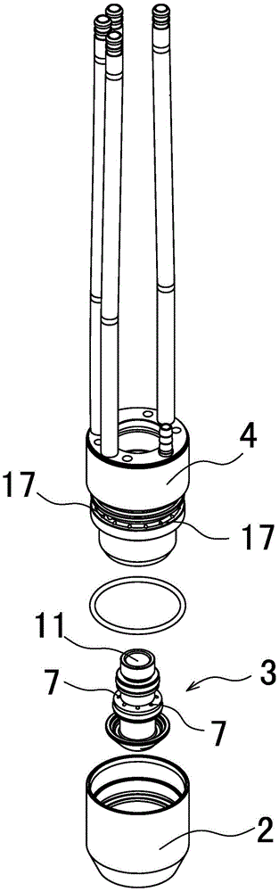
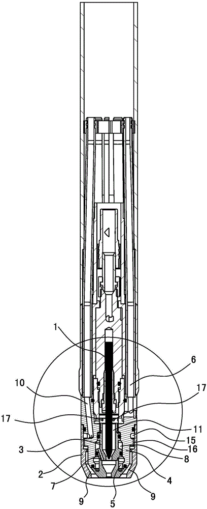
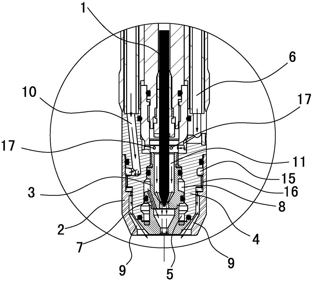
[0036] See attached figure 1 ~ attached Figure 7 As shown, including the gun handle, a tungsten electrode 1 is perforated along the axial direction of the gun handle, and one end of the tungsten electrode 1 is used as a discharge end, and a nozzle and a sheath 2 are arranged at the discharge end, wherein:

[0037] The main body of the nozzle is a cylinder with a hollow structure, and the hollow cavity of the hollow structure is used as an assembly cavity 11. The assembly cavity 11 is arranged along the axial direction of the cylinder, and the two ends of the assembly cavity 11 are opened on the two end faces of the cylinder. , the peripheral wall of the nozzle has a certain thickness.

[0038] The two ends of the assembly chamber 11 are divided into an inlet end and an outlet end along its axial direction, and the discharge end of the tungsten electrode 1 extends into the assembly chamber 11 from the inlet ...


PUM


Abstract

The invention provides an improved secondary compression type plasma welding gun. The improved secondary compression type plasma welding gun comprises a tungsten electrode, wherein a spray nozzle and a protective bush are arranged on the discharge end of the tungsten electrode; the spray nozzle is internally provided with an assembly cavity; an annular space is formed in the peripheral wall of the spray nozzle along the circumferential direction of the spray nozzle; the annular space serves as a water cooling space; the water cooling space is provided with a cooling water inlet and a cooling water outlet; a first-level compression gas circuit is arranged on the inlet end of the assembly cavity of the spray nozzle; a second-level compression gas hole between the inlet end and the outlet end is arranged on the peripheral wall of the spray nozzle, and the second-level compression gas hole is connected with the gas outlet end of a second-level compression gas circuit; a protective gas channel is arranged between the spray nozzle and the protective bush. According to the improved secondary compression type plasma welding gun, the electric arc discharged by the discharge end of the tungsten electrode is compressed twice by the plasma gas in the first-level compression gas circuit and the second-level compression gas circuit, so that the concentration of the electric arc is higher, the arc stiffness is stronger, the utilization rate of energy sources is higher, and the welding thickness of the plasma welding is greatly improved; the cooling on the first-level compression and the second-level compression is realized by one channel of the cooling water, and the structure is simple.

Description

technical field [0001] The invention relates to a plasma welding torch, in particular to an improved secondary compression plasma welding torch. Background technique [0002] Plasma welding is a welding method that utilizes a plasma arc as a heat source. The gas is dissociated by arc heating, and compressed when passing through the water-cooled nozzle at high speed, increasing the energy density and degree of dissociation to form a plasma arc. Its stability, calorific value and temperature are higher than ordinary arc, so it has greater penetration and welding speed. The gas forming the plasma arc and the shielding gas around it are generally argon. According to the material properties of various workpieces, helium or argon-helium, argon-hydrogen and other mixed gases are also used. [0003] The torch head of the existing plasma torch has only one water-cooled nozzle, which can only compress the plasma arc once, the arc concentration is not high, the stiffness is weak, th...

Claims


Application Information

Patent Timeline
Patent Type & Authority Patents(China)
IPC IPC(8): B23K10/02
CPCB23K10/02
Inventor 罗登峰谢彤王荣
Owner 苏州工业园区华焊科技有限公司
Why Eureka
Try Eureka