Clearance arrangement type continuous vacuum feeding machine

A vacuum feeder and discharge technology, applied in conveyors, conveying bulk materials, transportation and packaging, etc., can solve the problems of large waste of vacuum source, slow reduction, and unsmooth suction, and improve conveying efficiency. , The effect of solving powder explosion and avoiding dust pollution

Active Publication Date: 2014-12-17
欧才权
View PDF7 Cites 8 Cited by
  • Summary
  • Abstract
  • Description
  • Claims
  • Application Information

AI Technical Summary

Problems solved by technology

[0004] 1. The efficiency is low, the material is not unloaded when the material is sucked, and the material is not sucked when the material is unloaded, and the material is not conveyed continuously in time but is staggered;
[0005] 2. The delivery output is unstable, especially when the pneumatic jet vacuum generator is used as the vacuum source, because the vacuum depends on the compressed air to generate, and the pressure of the compressed air often fluctuates between 0.4~0.8MPa, so the vacuum degree of the vacuum generator is also As the compressed air pressure fluctuates from time to time, the conveying speed of the corresponding gap vacuum feeder will also change from time to time with the change of vacuum degree.
The square structure of the jet vacuum generator itself can only withstand the gap-type vacuum generation, and cannot withstand vacuum for a long time
[0006] The most economical is the electric vacuum pump, but the electric vacuum pump also has two defects when used as a gap vacuum feeder: 1) If the vacuum tube on the top of the vacuum feeder is equipped with a pneumatic three-way ball valve, there will be a large waste of vacuum source. The vacuum source is used to do work when the material is sucked, and the vacuum pump is switched by the three-way ball valve to suck the outside air without doing work when switching to feeding, which is a waste of resources; 2) If the vacuum tube on the top of the vacuum feeder is equipped

Method used


Image

  • Clearance arrangement type continuous vacuum feeding machine

Examples


Example Embodiment

[0026] In order to make the objectives, technical solutions and advantages of the present invention clearer, the present invention will be further described in detail below with reference to the accompanying drawings.

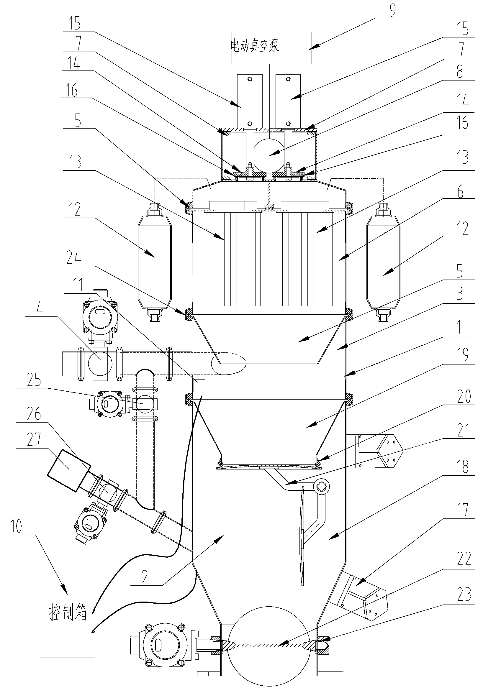
[0027] Such as figure 1 As shown, the inter-discharge type continuous vacuum feeder of the present invention includes a feeding device 1 and a discharging device 2 located below the feeding device 1. The feeding device 1 and the discharging device 2 Through the clamp 24 clamp connection, the tightness of the connection between the two is ensured. The feeding device 1 and the discharging device 2 are electrically connected with a control box 10 respectively, that is, they are respectively controlled by the intelligent control box 10.

[0028] Wherein, the feeding device 1 includes a feeding bin 3, a pneumatic suction butterfly valve 4, a separating cone 5, a filter bin 6 and an air duct mechanism 7; the pneumatic suction butterfly valve 4 is located on the side wall...


PUM


Abstract

The embodiment of the invention discloses a clearance arrangement type continuous vacuum feeding machine which comprises a feeding device and a discharging device below the feeding device. The feeding device comprises a feeding bin, a pneumatic material suction butterfly valve, a separation cone hopper, a filer bin and air channel mechanisms, the pneumatic material suction butterfly valve is arranged on the side wall of the feeding bin and used for carrying out feeding, the separation cone hopper is arranged in the feeding bin, the filter bin is arranged above the feeding bin, the air channel mechanisms are arranged above the separation cone hopper and are arranged in a bilateral symmetry mode, the structures of the air channel mechanisms are identical, and the two air channel mechanisms are connected with an electric vacuum pump through vacuum pipes. The electric vacuum pump is electrically connected with a control box. Through the clearance arrangement type continuous vacuum feeding machine, the aim of continuously and permanently conveying materials in a vacuum mode can be achieved without distance limits, the clearance arrangement type continuous vacuum feeding machine has the advantages of being high in conveying efficiency and high in vacuum source utilization rate, meanwhile, material suction and discharging can be kept smooth at constant speed, and dust leakage and potential safety hazards can be eliminated.

Description

technical field [0001] The invention relates to a vacuum feeder, in particular to an intermittent continuous vacuum feeder. Background technique [0002] Vacuum feeding machine is also called powder conveying system (abbreviated as PTS), and it is in the stage of general promotion at home and abroad. The equipment reduces dust pollution and saves labor. However, the vacuum feeders currently used at home and abroad are all gap-type, and there are problems such as unsmooth feeding, reverse spraying at the suction port, short conveying distance, and low efficiency. The powder transportation of high distance or large output often adopts positive pressure transportation, using high-pressure fan or compressed air to carry out positive pressure blowing to the long pipeline below which is equipped with related fans to uniformly feed materials to realize dilute phase transportation, and the end of the transportation needs to be equipped with a cyclone Separators, shut-off fans and ...

Claims


Application Information

Patent Timeline
IPC IPC(8): B65G53/24B65G53/58
Inventor 欧才权
Owner 欧才权
Why Eureka
Try Eureka