
Multifunctional air compressor

An air compressor and multi-functional technology, applied in the direction of electromechanical devices, mechanical equipment, machines/engines, etc., can solve the problems of reducing cooling wind, smooth air intake resistance, etc.

Active Publication Date: 2014-12-17
江西汉诺斯压缩机科技有限公司
View PDF7 Cites 7 Cited by
  • Summary
  • Abstract
  • Description
  • Claims
  • Application Information

AI Technical Summary

Problems solved by technology

[0002] At this stage, the products of air compressor manufacturers in various countries are already very efficient, and there is little room for further improvement in gas production and energy saving. The thermal oil generated during the working process of air compressors, the heat energy of gas and the radiant heat energy of equipment are currently The technology of air compressors in various countries has not been able to realize the recovery of three heats, and has the advantages of extremely high energy efficiency ratio of heat recovery, and the booster air compressor without increasing electricity consumption and the air compressor that does not use electricity to dry compressed air At present, there is no such thing, so in view of this, the applicant proposes a method that can realize three-heat recovery, increase gas production by more than 10%, and have low air intake resistance. By installing all energy-saving equipment in the chassis, the cooling air can be reduced. , cooling and power saving, high energy efficiency ratio; and has a good vibration reduction effect, no noise, a multi-functional air compressor that greatly reduces the temperature is indeed necessary

Method used


Image

  • Multifunctional air compressor

Examples


Embodiment Construction

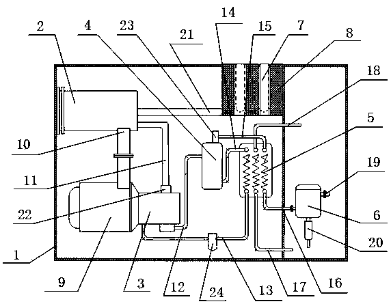
[0011] In this example, refer to figure 1 As shown, a multifunctional air compressor includes a chassis 1, and an air intake device (not shown), a motor (not shown), a booster air filter 2, a compressor 3, an oil and gas Separator 4, full heat recovery hot water machine 5 and centrifugal gas-liquid separator 6; the air inlet device (not shown) is provided with a filter bag 7 and a noise reduction pressure relief device 8, and the filter bag 7 is arranged on two Between the silencer and pressure relief device 8, the air outside the chassis 1 enters the chassis 1 after passing through the filter bag 7 to filter dust and the noise reduction and pressure relief device 8; the periphery of the motor (not shown) is provided with a motor cooling heat collector Cover 9, a heat collecting air duct 10 is arranged between the motor cooling heat collecting cover 9 and the pressurized air filter 2, the motor cooling heat collecting cover 9 collects the heat in the chassis 1 and transports i...


PUM


Abstract

The invention discloses a multifunctional air compressor which comprises a machine case, an air inlet device, a motor, a pressurization air filter, a compressor, an oil-gas separator, a total heat recovery water heater and a centrifugal gas-liquid separator. The air inlet device, the motor, the pressurization air filter, the compressor, the oil-gas separator, the total heat recovery water heater and the centrifugal gas-liquid separator are arranged in the machine case. Air outside the machine case enters the machine case after dust filtering of a filter bag and noise elimination of a noise elimination pressure relief device, heat in the machine case is collected by a motor cooling heat collection cover and is conveyed into the pressurization air filter through a heat collection and air supply pipe, heat energy of gas and radiation heat energy of equipment are recycled, and cold oil is conveyed to the compressor through an oil return pipe after hot oil in a separator engine oil conveying pipe is cooled by the total heat recovery water heater. According to the multifunctional air compressor, three kinds of heat are recycled, the generated gas rises and is improved by more than 10 percent, gas input is smooth and small in resistance, the whole energy-saving equipment is arranged in the machine case, air for cooling is reduced, cooling electricity consumption is reduced, electricity used by the air compressor is less, and the energy efficiency ratio is high. The good vibration and noise reduction and cooling effects are achieved.

Description

technical field [0001] The invention relates to an air compressor, in particular to a multifunctional air compressor used in the air compressor industry. Background technique [0002] At this stage, the products of air compressor manufacturers in various countries are already very efficient, and there is little room for further improvement in gas production and energy saving. The thermal oil generated during the working process of air compressors, the heat energy of gas and the radiant heat energy of equipment are currently The technology of air compressors in various countries has not been able to realize the recovery of three heats, and has the advantages of extremely high energy efficiency ratio of heat recovery, and the booster air compressor without increasing electricity consumption and the air compressor that does not use electricity to dry compressed air At present, there is no such thing, so in view of this, the applicant proposes a method that can realize three-hea...

Claims


Application Information

Patent Timeline
Patent Type & Authority Applications(China)
IPC IPC(8): F04B39/06F04B39/00F04B37/12F04B39/04H02K5/00F04B39/16
Inventor 任文建
Owner 江西汉诺斯压缩机科技有限公司
Learn More