

Visual soil freeze-thawing process test apparatus
A test device, freeze-thaw technology, applied in measuring devices, instruments, scientific instruments, etc., can solve problems such as uncertainty, achieve the effects of convenient observation, ensure uniformity, and overcome insufficient memory
- Summary
- Abstract
- Description
- Claims
- Application Information
AI Technical Summary
Problems solved by technology
Method used
Image

Examples
Embodiment Construction
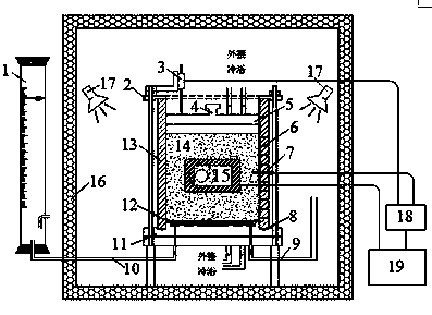
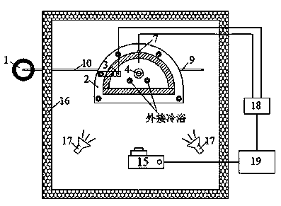
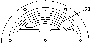
[0037] In conjunction with the accompanying drawings, the present invention is further described in detail through actual measurement examples:
[0038] Such as Figure 1-8 As shown, a visual soil freeze-thaw process test device, including 1. Mariotte bottle 2. Bracket 3. Displacement sensor 4. Handle 5. Temperature control top plate 6. Probe hole 7. Temperature sensor 8. Sealing ring 9. Water level adjustment pipe 10. Water guide pipe 11. Temperature control bottom plate 12. Filter paper 13. Semi-cylindrical sample tank 14. Soil sample 15. High resolution camera 16. Temperature control box 17. Adjustable light source 18. Data acquisition instrument 19. Electronic computer 20. Circulation tank. The temperature control box 16 is connected with an external compressor, and the temperature in the temperature control box 16 is controlled by the compressor, so that the temperature of the box body reaches the ambient temperature required for the test and remains stable; in the tempe...
PUM
 Abstract
Description
Claims
Application Information