In-situ monitoring method for rusting and stress state of reinforcing steel bar in concrete

A technology of stress state and inner steel bar, applied in the direction of measurement, measuring device, weather resistance/light resistance/corrosion resistance, etc. by measuring the changing force of optical properties of the material when it is stressed, which can solve the problem of insufficient test data and inability to judge the corrosion of steel bars. The status and effectiveness are yet to be verified, so as to achieve the effect of ingenious and reasonable structural design, solving the problem of steel corrosion monitoring, and clear design principles

Active Publication Date: 2014-12-17
UNIV OF SCI & TECH BEIJING +1
View PDF9 Cites 25 Cited by
  • Summary
  • Abstract
  • Description
  • Claims
  • Application Information

AI Technical Summary

Problems solved by technology

The specific methods are: (1) trapezoidal anode method, by arranging several anodes at different depths of the concrete layer, and monitoring the current between each anode and the same cathode to characterize the intrusion of chloride ions or the development of corrosion, thereby indirectly predicting the corrosion of steel bars, This kind of method has been applied in some engineering and laboratories, but the public test data is less, and the effectiveness needs to be confirmed
(2) The monitoring and detection methods represented by the half-cell potential method and the linear polarization method measure the potential or polarization resistance of each part of the steel bar on site to judge the possibility of corrosion everywhere, but these methods are not easy to implement for a long time Embedded online monitoring, and because the polarization resistance and potential are easily disturbed by various factors, the exact corrosion state of the steel bar cannot be judged
Polarization resistance measurement cannot determine the steel bar area affected by the disturbance signal, and often gives an overestimation of the actual corrosion degree. Another problem is that it is impossible to determine the appropriate excitation time, so that the current response measured during this time only contains Electrochemical information about the corrosion interface, independent of the e

Method used


Image

  • In-situ monitoring method for rusting and stress state of reinforcing steel bar in concrete
  • In-situ monitoring method for rusting and stress state of reinforcing steel bar in concrete
  • In-situ monitoring method for rusting and stress state of reinforcing steel bar in concrete

Examples


Embodiment 1

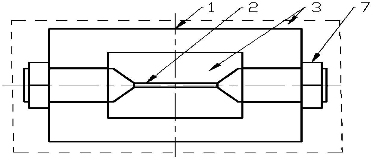
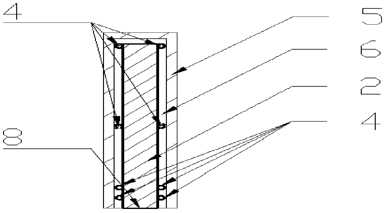
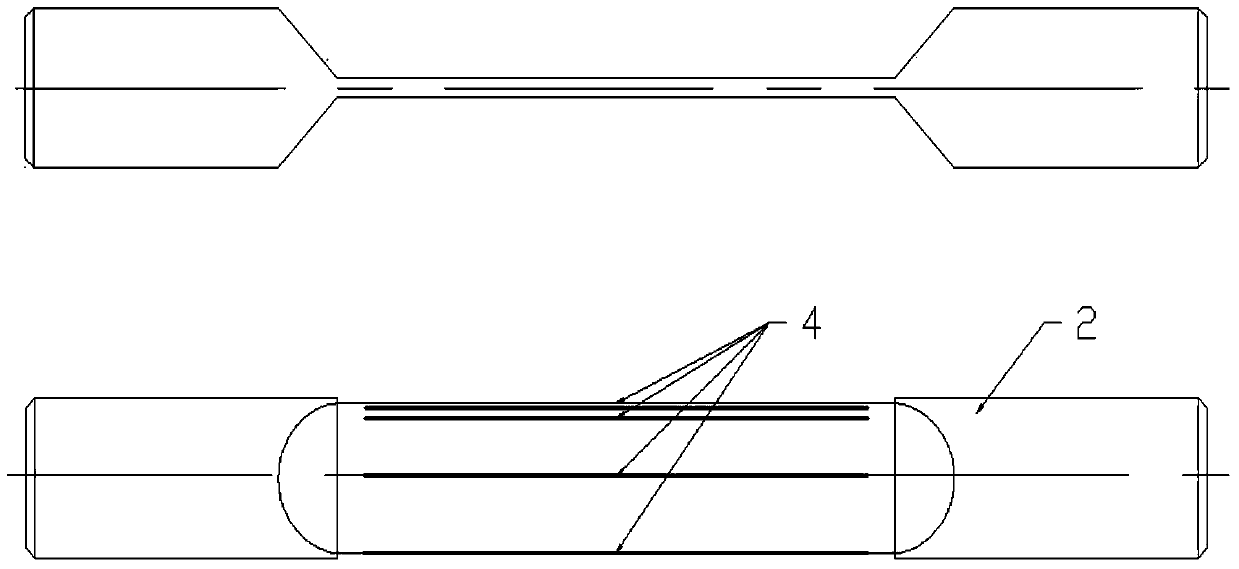
[0022] The steel bar corrosion sensor structure of the present invention is shown in Figure 1, wherein the middle steel bar sheet (2) is made of the same material as the longitudinally stressed steel bar in the concrete structure, and continuous strain measuring points (4) are arranged at different heights on the section of the middle steel bar sheet (2) ) ( Figure 1b , Figure 1c As shown), the continuous strain measurement point (4) adopts high-spatial-resolution distributed optical fiber, which is pasted at different heights of the steel sheet section by high-performance glue, and is connected with the corresponding demodulator through the transmission optical fiber, and the high-spatial-resolution distributed optical fiber can be continuously monitored in the length direction ( Figure 1c Shown) the average strain per millimeter of length, reserve a section of optical fiber close to the loading nut that is not attached to the steel wire sheet (not deformed together with ...

Embodiment 2

[0023] Example 2 : The structure of the present invention is shown in Figure 1, wherein middle steel bar sheet (2) adopts the same material as the longitudinally stressed steel bar in the concrete structure, and continuous strain measuring points (4) are arranged at different heights on the middle steel bar sheet ( Figure 1b , Figure 1c shown), the continuous strain measuring point (4) adopts a chain strain gauge group (such as HBM KY11-1 / 120), each chain strain gauge group has 10 measuring gauges, and 1 temperature compensation gauge for temperature compensation (The monitored strain below is the strain after compensation). The grid length of a single strain gauge is 0.6mm, and the center distance between adjacent strain gauges is 1mm. It is pasted at different cross-sectional heights of the steel sheet with high-performance glue. The strain gauge passes through the welding terminal, the wire and the strain gauge. connection, the chain strain gauge group can continuously mo...


PUM


Abstract

The invention relates to an in-situ monitoring method for rusting and a stress state of a reinforcing steel bar in concrete. The method comprises the following steps of establishing an automatic prestress balance system, applying initial prestress to a reinforcing steel bar sheet which is made of a same material with that of the reinforcing steel bar in the concrete, and embedding the reinforcing steel bar sheet into a concrete structure; arranging continuous strain measuring points on different heights of the reinforcing steel bar sheet, and monitoring the stress state of the area in which the strain measuring points are arranged; and forming a plane stress state on the reinforcing steel bar sheet, generating stress concentration after the reinforcing steel bar sheet is locally corroded, and reflecting the initial rusting time, rusting rate and rusting degree of the reinforcing steel bar according to the strain variation of the continuous measuring points on the different heights of the cross section. The reinforcing steel bar sheet can be embedded in different depths from the surface of the concrete, and the monitoring and rusting risk evaluation on the rusting degree of the reinforcing steel bar and the stress state of the embedded area in the different depths can be realized. The method is not subjected to the influence of ambient factors such as different ions, temperature and humidity in the concrete and is particularly suitable for evaluating the rusting risk and the rusting degree of the reinforcing steel bar in the reinforced concrete structure in a wave erosion environment wave splashing area and a tidal range zone.

Description

technical field [0001] The invention belongs to the health monitoring technology of civil engineering structures, in particular relates to the durability of reinforced concrete structures, and is applied to the corrosion monitoring and durability evaluation of reinforced concrete structures. Background technique [0002] Existing technology: Steel bar corrosion is the main reason for the durability damage of reinforced concrete structures. At present, the steel bar corrosion monitoring technology is mainly divided into two methods: physical and electrochemical. Electrochemical means are widely used, mainly around the measurement of the corrosion current generated during the steel corrosion process or the potential difference between electrodes to characterize the possibility of corrosion. The specific methods are: (1) trapezoidal anode method, by arranging several anodes at different depths of the concrete layer, and monitoring the current between each anode and the same cat...

Claims


Application Information

Patent Timeline
IPC IPC(8): G01N17/00G01L1/24
Inventor 兰成明肖珣孙冬柏李惠袁杰周文松
Owner UNIV OF SCI & TECH BEIJING
Why Eureka
Try Eureka