
End sealing method for low-voltage foil type coil of dry type transformer

A technology of dry-type transformers and low-voltage coils, applied in the field of transformers, can solve problems affecting the performance and appearance quality of transformers, shorten the service life of transformers, etc., and achieve the effect of improving appearance quality and electrical performance, clear edges and corners, and bright color

Inactive Publication Date: 2014-12-17
NINGBO AUX HIGH TECH
View PDF5 Cites 4 Cited by
  • Summary
  • Abstract
  • Description
  • Claims
  • Application Information

AI Technical Summary

Problems solved by technology

This seriously affects the performance and appearance quality of the transformer and shortens the service life of the transformer

Method used


Image

  • End sealing method for low-voltage foil type coil of dry type transformer
  • End sealing method for low-voltage foil type coil of dry type transformer

Examples


Embodiment 1

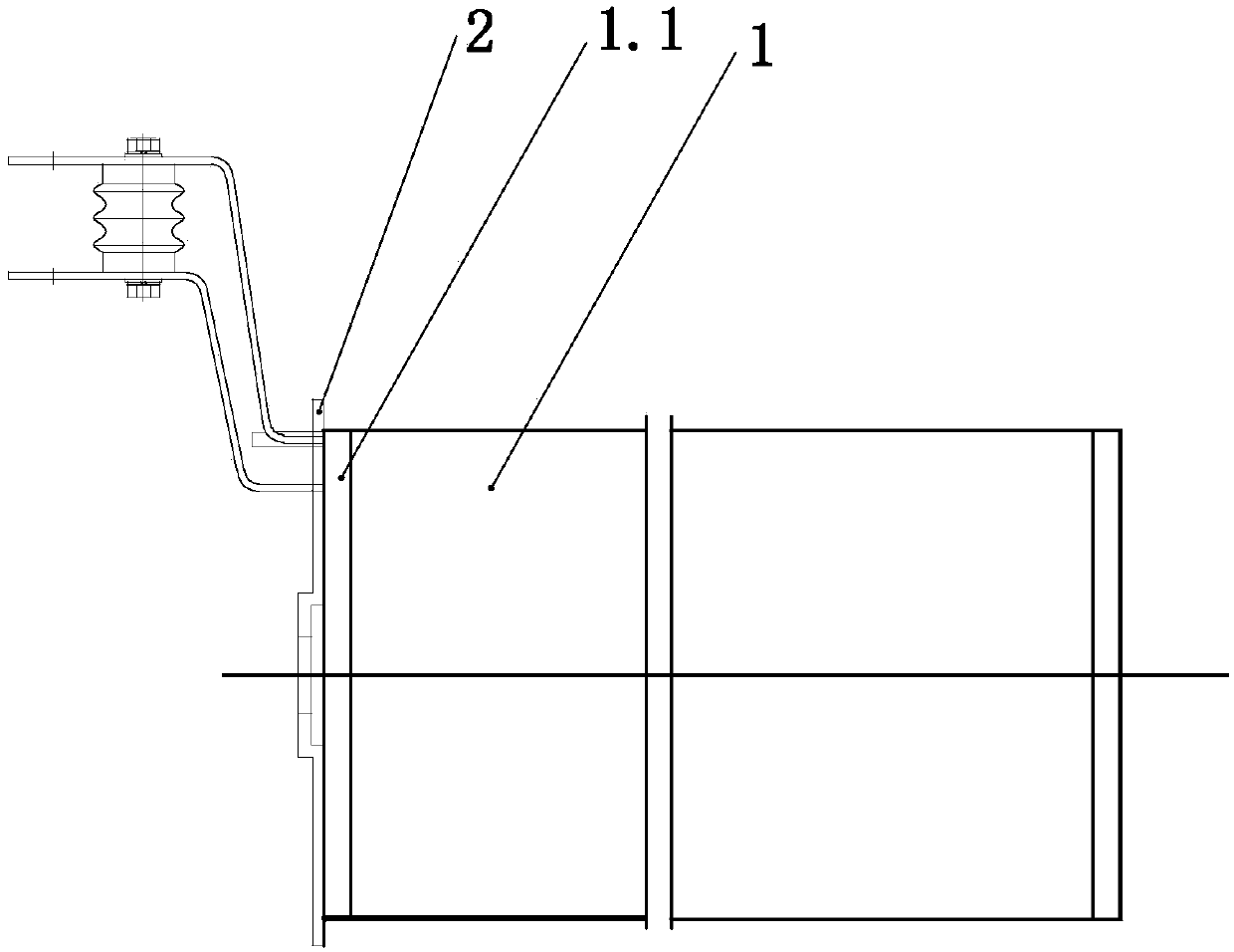
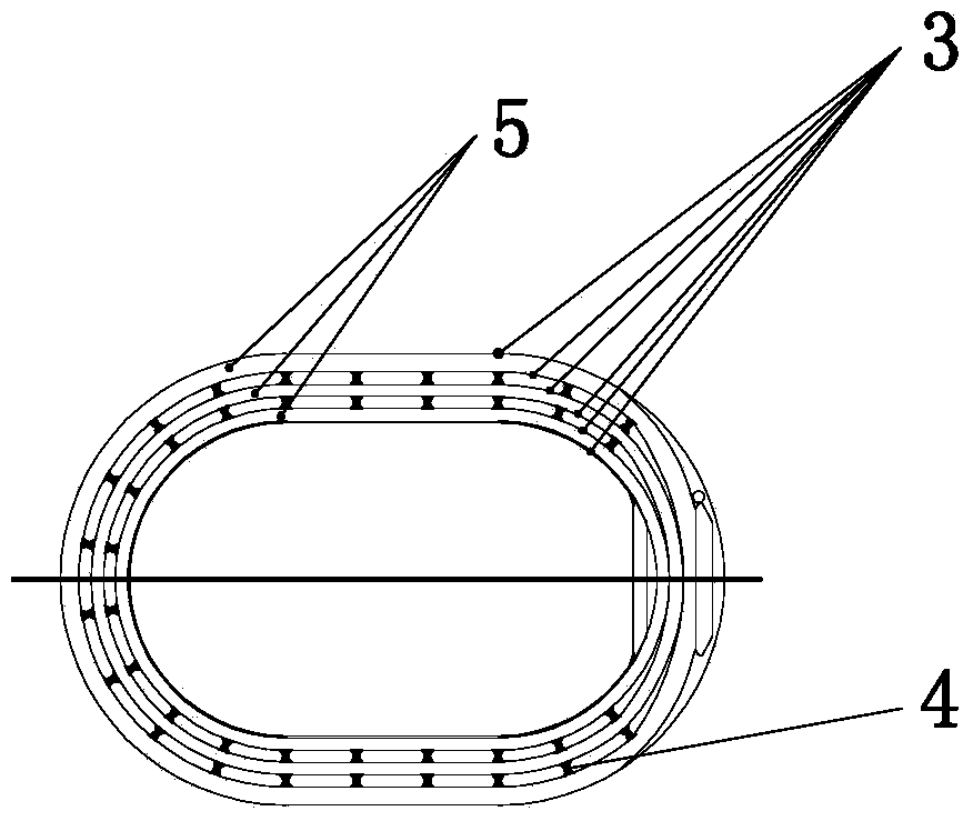
[0020] Embodiment one: if figure 1 , figure 2 As shown, the dry-type transformer low-voltage foil coil end sealing method of the present invention includes the following specific steps:

[0021] (1) When the low-voltage coil 1 is winding, the upper end surface 1.1 does not place the end insulation made of epoxy resin prepreg, and places a thickness of 0.5mm on the innermost layer, outermost layer and both sides of the stay 4 The epoxy board 3, the epoxy board 3 should be close to the baffle plate 2, and the pouring groove 5 is formed between the adjacent epoxy boards 3; the end insulation made of the epoxy resin prepreg is a market purchase product;

[0022] (2) According to the process requirements, the low-voltage coil 1 is cured in an oven, and after leaving the oven, the low-voltage coil 1 is demoulded when the temperature of the low-voltage coil 1 drops below 40°C;

[0023] (3), apply glass glue at the slit of each pouring groove 5; this glass glue is a market purchase...

Embodiment 2

[0031] Embodiment two: if figure 1 , figure 2 As shown, the dry-type transformer low-voltage foil coil end sealing method of the present invention includes the following specific steps:

[0032] (1) When the low-voltage coil 1 is winding, the upper end surface 1.1 does not place the end insulation made of epoxy resin prepreg, and places a thickness of 0.5mm on the innermost layer, outermost layer and both sides of the stay 4 The epoxy board 3, the epoxy board 3 should be close to the baffle plate 2, and the pouring groove 5 is formed between the adjacent epoxy boards 3; the end insulation made of the epoxy resin prepreg is a market purchase product;

[0033] (2) According to the process requirements, the low-voltage coil 1 is cured in an oven, and after leaving the oven, the low-voltage coil 1 is demoulded when the temperature of the low-voltage coil 1 drops below 40°C;

[0034] (3), filling the non-alkali glass ribbon at the gap of each pouring groove 5; the alkali-free gl...


PUM

PropertyMeasurementUnit
Thicknessaaaaaaaaaa

Abstract

The invention discloses an end sealing method for a low-voltage foil type coil of a dry type transformer. The end sealing method comprises the following specific steps of (1) forming a pouring groove (5) when a low-voltage coil (1) is wound; (2) solidifying and demolding; (3) painting glass cement or filling alkali-free glass tape; (4) preheating; (5) preparing high-temperature-resisting normal temperature resin; (6) carrying out degasification processing; (7) fully solidifying the high-temperature-resisting normal temperature resin; (8) polishing the low-voltage coil to be in a drawing size; (9) painting mixture of putty and a curing agent in the position of a bubble generated by resin reaction, and smoothing the bubble; (10) cleaning the low-voltage coil (1). According to the end sealing method disclosed by the invention, an uneven surface, a hole and a gap of the low-voltage coil are successfully removed, the upper end surface of the produced low-voltage coil is bright in color and clear in corner angle, the end sealing is not subjected to warping and cracking at 155 DEG C, and the appearance quality and the electrical performance of the low-voltage coil are greatly increased.

Description

technical field [0001] The invention relates to the technical field of transformers, in particular to an end sealing method for low-voltage foil coils of dry-type transformers. Background technique [0002] The manufacture of low-voltage foil coils for dry-type transformers is divided into three processes: winding, shaping and curing, and end sealing. When making the upper end seal of the coil, the normal temperature resin material A and material B are prepared in proportion, and then poured into the groove of the upper end surface of the coil, and the excess normal temperature resin at the air passage is cleaned. Finally, after the resin is completely cured at room temperature, it is smoothed with a grinder and sprayed with red paint. If the temperature rise of the transformer exceeds 130°C during the operation, the normal temperature resin will have layers, cracks, etc. (here, can you emphasize the key temperature of 130°C, and then analyze it in detail below) resulting i...

Claims


Application Information

Patent Timeline
IPC IPC(8): H01F41/04
Inventor 王诚
Owner NINGBO AUX HIGH TECH
Learn More