Multi-phase reluctance machine

A reluctance motor and excitation technology, applied in electrical components, electromechanical devices, magnetic circuit static parts, etc., can solve the problem of low torque density of the motor, and achieve widening the range of constant power speed regulation, high efficiency, and improved utilization. Effect

Active Publication Date: 2014-12-17
HARBIN INST OF TECH
View PDF6 Cites 61 Cited by
  • Summary
  • Abstract
  • Description
  • Claims
  • Application Information

AI Technical Summary

Problems solved by technology

[0004] The purpose of the present invention is to solve the problem that the existing switched reluctance motor can only obtain unidirectional

Method used


Image

  • Multi-phase reluctance machine
  • Multi-phase reluctance machine
  • Multi-phase reluctance machine

Examples


specific Embodiment approach 1

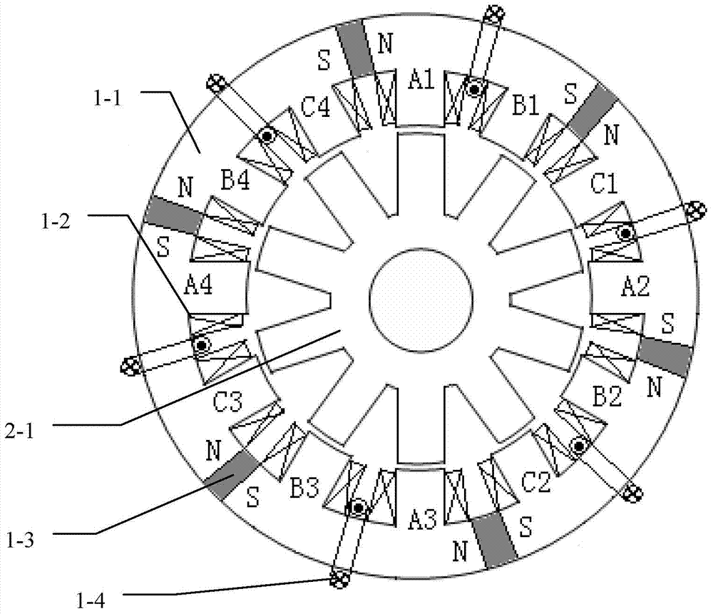
[0046] Specific implementation mode 1: the following combination Figure 1 to Figure 9 Explaining this embodiment, the multi-phase reluctance motor of this embodiment includes a stator and a rotor. An air gap is formed between the stator and the rotor. The stator includes an armature core 1-1, an armature winding 1-2, and an excitation unit.

[0047] The armature core 1-1 is cylindrical, and the air gap side surface of the armature core 1-1 is provided with a plurality of axial slots to form a structure in which the stator poles and the stator slots are arranged at intervals in the circumferential direction; each stator pole An armature coil is wound, and the armature coils of the same phase are connected in series along the circumferential direction of the armature core 1-1 to form a one-phase armature winding, and the multi-phase winding composed of all phase armature windings is the armature winding 1-2;

[0048] The excitation unit is arranged on the yoke of the armature core 1...

specific Embodiment approach 2

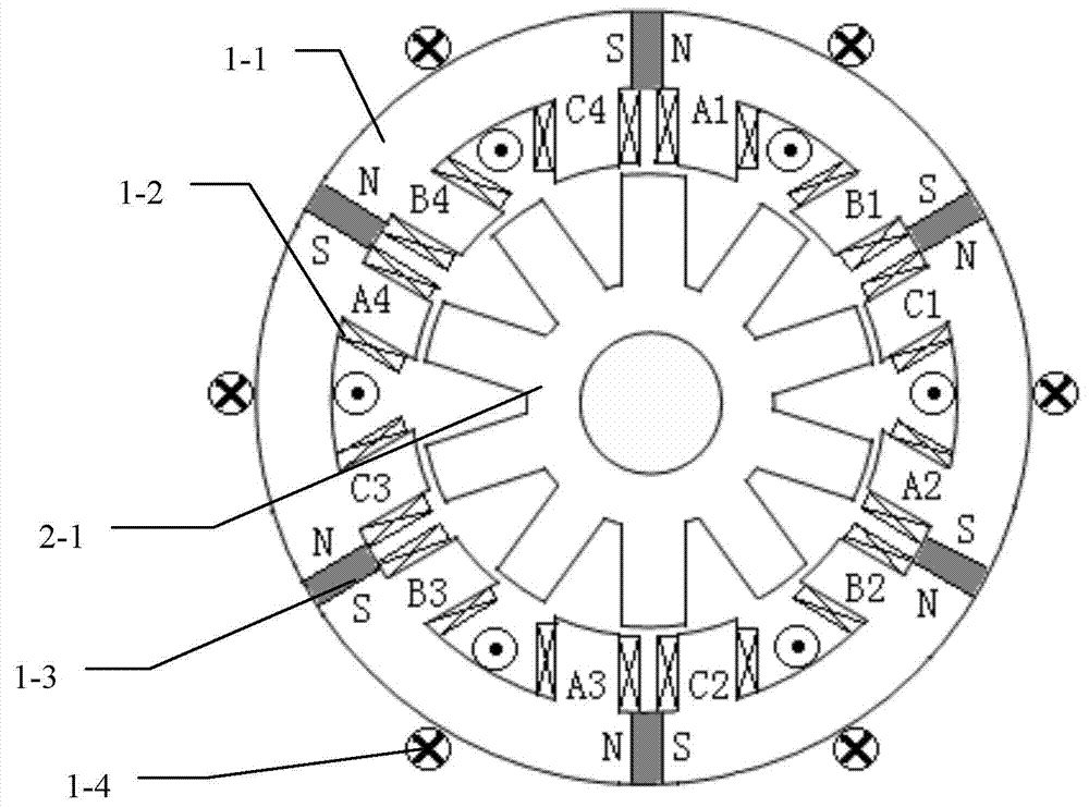
[0050] Specific implementation manner 2: the following combination figure 1 with figure 2 This embodiment will be described. This embodiment will further explain the first embodiment. The excitation unit is composed of a main permanent magnet excitation unit 1-3 and an electric excitation unit 1-4.

[0051] The main permanent magnet excitation unit 1-3 includes a plurality of plate-shaped main permanent magnets, and the electric excitation unit 1-4 is composed of a plurality of excitation coils in series, and the plate-shaped main permanent magnet is embedded in the armature core 1 corresponding to the bottom of the stator slot. -1 In the middle of the yoke, each excitation coil is wound around the middle of the armature core 1-1 yoke corresponding to the bottom of a stator slot. All the excitation coils have the same winding direction; the plate-shaped main permanent magnet and the excitation coil are along the armature core 1 -1 The yokes are arranged alternately;

[0052] The ...

specific Embodiment approach 3

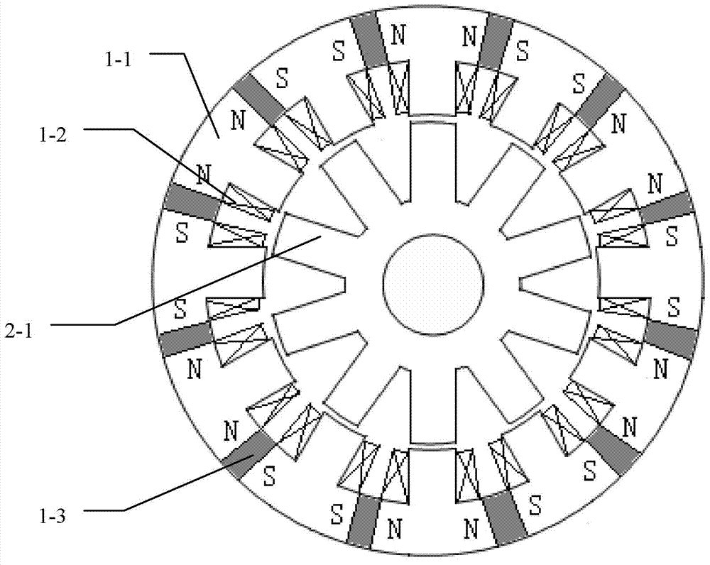
[0059] Specific implementation manner three: the following combination image 3 This embodiment will be described. This embodiment will further explain the first embodiment. The excitation unit is the main permanent magnet excitation unit 1-3, and the main permanent magnet excitation unit 1-3 includes a plurality of flat main permanent magnets, and each stator slot bottom A plate-shaped main permanent magnet is embedded in the middle of the corresponding armature core 1-1 yoke;

[0060] The plate-shaped main permanent magnets are magnetized tangentially along the circumference, and the magnetizing directions of adjacent plate-shaped main permanent magnets are opposite;

[0061] The plate-shaped main permanent magnet is a rare earth permanent magnet.

[0062] In this embodiment, the plate-shaped main permanent magnet is made of a rare earth permanent magnet with high remanence and high coercivity.

[0063] image 3 Among them, there are a total of 12 flat main permanent magnets.


PUM


Abstract

The invention belongs to the technical field of motors, discloses a multi-phase reluctance machine and solves the problem that only works for a half electric cycle, the conventional switch reluctance machine can acquire the one-way torque, thus the torque density of the motor is low. An armature core is in a cylinder shape. A plurality of axial slots are formed in the side surface of an airspace of the armature core to form a structure in which stator poles and stator slots are spaced along a peripheral direction. Each stator pole is wounded by an armature coil. Along the peripheral direction of the armature core, co-phasal armature coils are sequentially connected to for a phase armature winding, and a multi-phase winding, composed of the phase armature windings, is an armature winding. Excitation units are arranged on a yoke portion of the armature core or the stator poles. A rotator comprises a rotator core. A plurality of axial slots are formed in the side surface of an air gap of the rotator core to form a structure in which rotator poles and rotator slots are spaced along the peripheral direction.

Description

Technical field [0001] The invention relates to a multiphase reluctance motor and belongs to the technical field of motors. Background technique [0002] The structure of the traditional switched reluctance motor is as Picture 10 As shown, the stator and rotor of the motor are both salient pole structures, and the windings are concentrated windings with short ends. By sequentially energizing the stator field windings, the stator poles interact with the rotor poles to generate torque. Since the rotor has neither windings nor permanent magnets, it is only laminated by silicon steel sheets, which can withstand high mechanical stress and is suitable for high-speed operation; at the same time, the motor has low cost, simple structure, reliable operation, and high-efficiency speed regulation range Wide; high starting torque, low starting current; able to adapt to harsh working environments such as high temperature, high humidity, strong vibration, large overload, high speed, etc., and...

Claims


Application Information

Patent Timeline
IPC IPC(8): H02K29/03H02K1/12H02K1/17H02K3/28H02K1/24
Inventor 寇宝泉杨小宝谢逸轩贺铁锐邵一
Owner HARBIN INST OF TECH
Why Eureka
Try Eureka