Cascaded resonance DC-DC conversion circuit combined with inductor and capacitor
A DC-DC and conversion circuit technology, applied in the field of two-stage cascaded current source input type resonant DC-DC circuit, can solve the problems of affecting power density, power density reduction, and large number of components, so as to improve service life, Effect of reducing switching loss and reducing energy consumption
- Summary
- Abstract
- Description
- Claims
- Application Information
AI Technical Summary
Problems solved by technology
Method used
Image
Examples
Embodiment 1
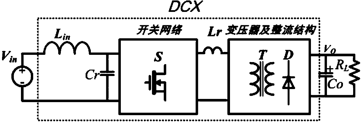
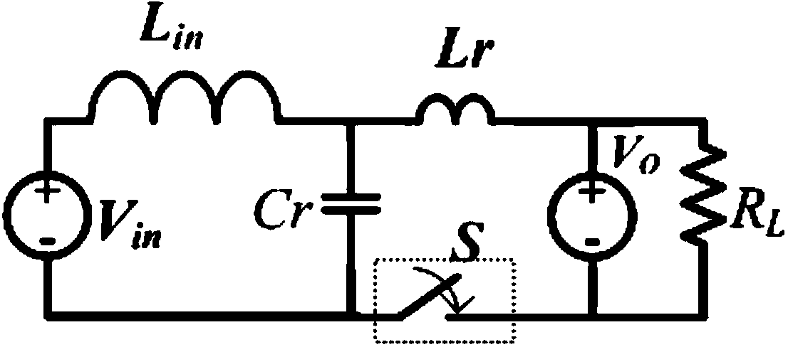
[0048] By adopting the two-stage cascaded DC-DC converter circuit of the present invention, the output voltage can be adjusted, the power density can be improved, and the power loss of the switching device can be reduced. The invention can reduce the energy consumption of the circuit, save energy, improve the energy conversion efficiency, reduce the heat generation of the power switching device, improve the working stability of the circuit, and increase the service life of the device and the circuit. The invention is suitable for DC-DC DC voltage conversion power supply circuit. Embodiment 1: A composite Boost cascaded full-bridge resonant DC-DC circuit, the secondary side of the high-frequency transformer adopts a full-bridge rectification structure and a voltage doubler rectification structure, and its circuit structure is as follows Figure 8 and Figure 9 shown.
[0049] The specific connection method is: the positive end of the input voltage source is connected to one e...
Embodiment 2
[0052] Embodiment 2: A composite Boost cascaded push-pull resonant DC-DC circuit, the high-frequency transformer adopts a full-bridge rectification structure and a voltage doubler rectification structure, and its circuit structure is as follows Figure 12 and Figure 13 shown.
[0053] The specific connection method is: the positive end of the input voltage source is connected to one end of the input inductor Lin; the resonant capacitor is the output capacitor of the previous stage; there are two windings on the primary side of the transformer, the end with the same name of the first winding of the original side and the end of the second winding with the same name The non-identical terminal of the first winding is connected to one end of the switch tube S1, the same-named terminal of the second winding is connected to one end of the second switch tube S2, and the other end of the two switches is connected to the input negative terminal; the equivalent leakage inductance of the...
Embodiment 3
[0056] Embodiment 3: A composite Boost cascaded push-pull forward resonant DC-DC circuit. The secondary side of the high-frequency transformer adopts a full-bridge rectification structure and a voltage doubler rectification structure. The circuit structures are as follows: Figure 16 and Figure 17 shown.
[0057] The specific connection method is: the positive end of the input voltage source is connected to one end of the input inductor Lin; the first resonant capacitor Cr1 is the output capacitor of the previous stage; After one end of the tube is connected; the non-identical end of the first winding is connected to one end of the switch tube S1, and the non-identical end of the second winding is connected to the other end of the second switch tube S2; the other end of the first switch and the second winding The same-named terminal of the input is connected to the negative terminal of the input. The other end of the two switches is connected to the input negative end; one ...
PUM
 Abstract
Description
Claims
Application Information
 - R&D
- Intellectual Property
- Life Sciences
- Materials
- Tech Scout
- Unparalleled Data Quality
- Higher Quality Content
- 60% Fewer Hallucinations
Browse by: Latest US Patents, China's latest patents, Technical Efficacy Thesaurus, Application Domain, Technology Topic, Popular Technical Reports.
© 2025 PatSnap. All rights reserved.Legal|Privacy policy|Modern Slavery Act Transparency Statement|Sitemap|About US| Contact US: help@patsnap.com


