
Air suspension

An air suspension, air spring technology, applied in suspension, elastic suspension, transportation and packaging, etc., can solve the requirements of high strength performance of guide spring, unfavorable improvement of vehicle ride comfort, high stiffness of guide spring 03, etc. problems, to achieve the effect of compact structure, reduced motion interference, and reduced stiffness

Active Publication Date: 2014-12-24
ANHUI JIANGHUAI AUTOMOBILE GRP CORP LTD
View PDF6 Cites 8 Cited by
  • Summary
  • Abstract
  • Description
  • Claims
  • Application Information

AI Technical Summary

Problems solved by technology

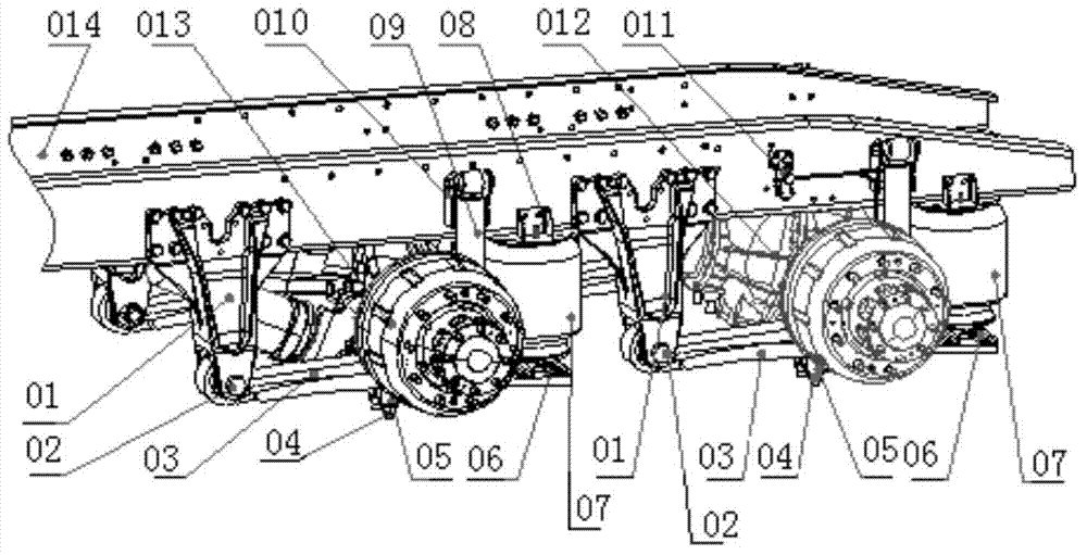
[0004] The air suspension in the prior art has the following problems: the guide spring 03 has the functions of bearing and guiding. Although the structure is simple, it requires high strength and performance of the guide spring 03, and the suspension device is relatively heavy, which is not conducive to the stability of the vehicle. Weight reduction; In addition, the rigidity of the guide spring 03 is relatively large, which is not conducive to the improvement of the ride comfort of the vehicle; during the movement, most parts such as the axle and air spring are located above the guide spring 03, and the guide spring 03 has Larger motion interference, and makes the space occupied; the guide spring 03 has to bear vertical load, lateral load and torsional load, the reliability is low; the shock absorber 09 is located between the axle 013 and the air spring 07. The heat generated during the process will cause thermal damage to the air spring 07

Method used


Image

  • Air suspension
  • Air suspension
  • Air suspension

Examples


Embodiment Construction

[0036] Next, specific embodiments of the present invention will be further described in detail with reference to the accompanying drawings, and in the following description, the up-down direction is defined as the vertical direction, the front-rear direction is defined as the longitudinal direction, and the left-right direction is defined as the horizontal direction.

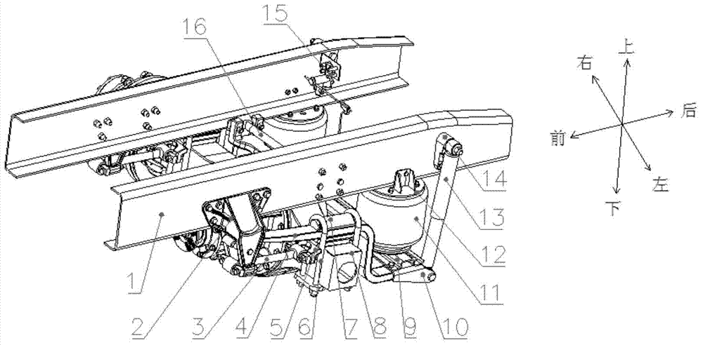
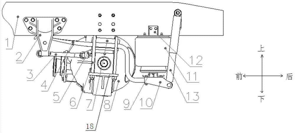
[0037] combine Figure 2 to Figure 5 , the air suspension in this embodiment includes: vehicle frame 1, front end bracket 2, guide thrust rod 3, bearing spring 4, guide thrust rod support 5, saddle bolt 6, leaf spring cover plate 7, axle 8, crossbeam 9. Rear end bracket 10, air spring 11, shock absorber 13, height valve assembly 15 and lateral thrust rod 16. The vehicle frame 1 has a pair of longitudinal beams extending in the front-rear direction and parallel to each other. From image 3 It can be seen more clearly that the bearing spring 4 is roughly Z-shaped, the front end of the bearing spring 4 is connect...


PUM


Abstract

The invention provides an air suspension which comprises a frame, a front-end support, a rear-end support, a bearing spring, an air spring, a shock absorber, an axle, a beam, a guide thrust rod and a transverse thrust rod. The bearing spring is of a Z shape, the front end of the bearing spring is connected with the front-end support, and the rear end of the bearing spring is connected with the rear-end support; the front-end support is installed on the frame, the upper end of the shock absorber is hinged to the frame, the lower end of the shock absorber is hinged to the rear-end support, and therefore the bearing spring is provided with a first part close to the frame and a second part away from the frame; the frame is suspended below the first part, the beam is installed above the second part, and the air spring is installed between the frame and the beam; one end of the guide thrust rod is connected with the front-end support and the other end of the guide thrust rod is connected with the axle; one end of the transverse thrust rod is connected with the axle and the other end of the transverse thrust rod is connected with the frame. The air suspension is compact in structure and good in smoothness.

Description

technical field [0001] The invention relates to the field of automobile suspension, in particular to an air suspension. Background technique [0002] With the further implementation of the country's maximum total mass limit standard for heavy-duty trucks, the lightweight and fuel consumption reduction of heavy-duty commercial vehicles has become the main direction of the development of heavy-duty commercial vehicles. The air suspension device has the characteristics of light weight, which can greatly reduce the weight of the whole vehicle. Compared with the traditional air suspension, the composite air suspension device has the characteristics of low cost, simple mechanism and convenient operation. [0003] Air suspension in the prior art such as figure 1 As shown, it includes: 01, guide spring bracket, 02, guide spring bolt, 03, guide spring assembly, 04, saddle bolt, 05, shock absorber lower bracket, 06, beam, 07, air spring, 08, air Spring bracket, 09, shock absorber a...

Claims


Application Information

Patent Timeline
IPC IPC(8): B60G15/08
Inventor 李海波居刚董金国
Owner ANHUI JIANGHUAI AUTOMOBILE GRP CORP LTD
Learn More