Vertical-shaft maglev wind-driven power generator

A technology of wind power generators and magnetic levitation, applied in wind power generators, wind power motor combinations, wind power generators at right angles to the wind direction, etc. Increase the manufacturing and operating costs of wind turbines to achieve the effect of high wind energy utilization, simple structure, and simplified structure

Active Publication Date: 2014-12-24
扬中市冠捷科创有限公司
View PDF8 Cites 8 Cited by
  • Summary
  • Abstract
  • Description
  • Claims
  • Application Information

AI Technical Summary

Problems solved by technology

Due to the use of a large number of permanent magnets in this published patent document, it is bound to increase the manufacturing cost of the magnetic levitation wind power generator, and the assembly accuracy is also greatly tested, and it is also not conducive to the development of large-scale magnetic levitation wind power generator research and development.
The publication number is CN201714584U, and the patent document titled "A New Type of Magnetic Suspension Wind Power Generator", the front and rear radial magnetic bearings, and the axial magnetic bearings are all active magnetic suspension bearings, which not only increases the scale of the magnetic suspension bearing control system, It also greatly increases the manufacturing and operating costs of wind turbines, which is not conducive to the popularization and application of magnetic levitation support technology in wind turbines
The publication number is CN101701573A, and the patent document titled "A Horizontal Axis Suspension Wind Power Generator" adopts a magnetic ring with a conical structure. Due to the complicated relationship between the offset and the force of the conical structure, it requires high installation accuracy. And there will be damage, which is not conducive to the accurate design of the magnetic suspension support structure during the design process

Method used


Image

  • Vertical-shaft maglev wind-driven power generator
  • Vertical-shaft maglev wind-driven power generator
  • Vertical-shaft maglev wind-driven power generator

Examples


Embodiment Construction

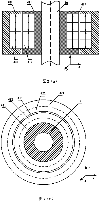
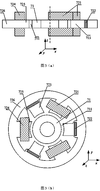
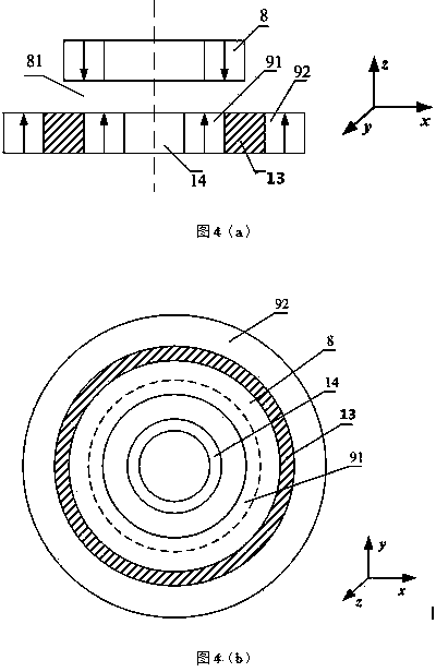
[0031] like figure 1 As shown, a vertical axis magnetic levitation wind power generator is composed of a stationary part and a rotating part, and is characterized in that the stationary part includes an upper end protection bearing 3, a static magnetic ring part 42 of a radial permanent magnetic bearing, and a generator stator from top to bottom. 62. Six-pole radial hybrid magnetic bearing stator 72, lower end protective bearing 5, inner magnetic ring 91 at the lower end of the axial permanent magnetic bearing, outer magnetic ring 92 at the lower end of the axial permanent magnetic bearing, magnetic isolation ring 13, wind turbine casing 12 and wind turbine tower 15;

[0032] The rotating part includes from top to bottom: blade 1, hub 2, wind turbine shaft 10, baffle plate 11, radial permanent magnetic bearing moving magnetic ring part 41, generator rotor 61, six-pole radial hybrid magnetic bearing rotor 71, A permanent magnet ring 8 at the upper end of the axial permanent ma...


PUM


Abstract

The invention relates to a vertical-shaft maglev wind-driven power generator. The vertical-shaft maglev wind-driven power generator consists of blades, a rotating shaft, a power generator, a radial permanent magnetic bearing, a radial hybrid magnetic bearing, an axial permanent magnetic bearing, an upper protection bearing and a lower protection bearing. Radial two degrees of freedom of the upper end of a wind turbine are realized through the permanent magnetic bearing, the power generator is arranged in the middle, the lower end is supported by the radial hybrid magnetic bearing in a two-degree-of-freedom manner, the axial permanent magnetic bearing is arranged at the bottom and is used for supporting the entire weight of the wind turbine, and when external disturbing force is very small and close to zero, five-degree-of-freedom stable levitation of a main shaft system can be realized without consuming any electric power. Since the rotating shaft supporting structure only has the radial hybrid magnetic bearing at the lower end, the radial two-degree-of-freedom active control of the lower end can be realized by changing current in a coil. The maglev supporting scheme fundamentally eliminates mechanical friction caused by the traditional mechanical supporting manner, reduces the starting resistance moment, thus reduces the wind speed for starting the wind-driven power generator and improves the utilization ratio of wind energy.

Description

technical field [0001] The invention belongs to the technical field of wind power generation, and relates to a vertical axis wind power generator, in particular to a vertical axis wind power generator with a small magnetic suspension support structure. Background technique [0002] With people's strong pursuit of wind energy development and utilization, all kinds of wind generators have been vigorously developed. Traditional wind generators often use mechanical bearings to support the rotor system. When the fan is running, the rotating part and the static part are seriously The friction and wear of the fan increase the maintenance cost of the fan. At the same time, the starting torque and starting wind speed are also relatively large, which seriously affects the efficiency of wind energy conversion. In order to make full use of the wind energy resources in low wind areas and reduce the starting wind speed of the wind turbine, the rotor is suspended in the space by using magn...

Claims


Application Information

Patent Timeline
Patent Type & Authority Applications(China)
IPC IPC(8): F03D9/00F03D3/00F16C32/04
CPCF16C2360/31Y02E10/74
Inventor 朱熀秋钱一赵俊峰曾润章朱利东刘元莹陈晓
Owner 扬中市冠捷科创有限公司
Why Eureka
Try Eureka