Liquid level sensor and connecting and fixing method of outer pipe of liquid level sensor

A technology of liquid level sensor and fixing method, which is applied to the liquid level indicator, liquid level indicator, liquid/fluid solid measurement and other directions of physical variable measurement, which can solve the problem of unsightly appearance of the product, corrosion at the weld, affecting the liquid level Sensor security and reliability issues to achieve the effect of a solid connection

Active Publication Date: 2014-12-24
FIRSTRATE SENSOR
View PDF7 Cites 0 Cited by
  • Summary
  • Abstract
  • Description
  • Claims
  • Application Information

AI Technical Summary

Problems solved by technology

Because the weld seam is exposed, not only the appearance of the product is not beautiful, but also because there are many impurities and dust in the air, it is easy to cause corrosion at the weld seam, and there are problems such as the connection of the outer pipe is not firm, which affects the actual use of the liquid level sensor. safety and reliability

Method used


Image

  • Liquid level sensor and connecting and fixing method of outer pipe of liquid level sensor
  • Liquid level sensor and connecting and fixing method of outer pipe of liquid level sensor
  • Liquid level sensor and connecting and fixing method of outer pipe of liquid level sensor

Examples


Embodiment 1

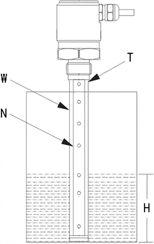
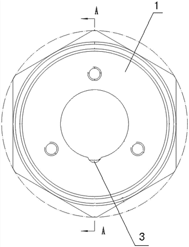
[0023] refer to figure 2 , image 3 and Figure 4 , a liquid level sensor, including a threaded joint 1 and an outer tube W used as an external electrode, the outer wall of the upper end of the threaded joint is provided with threads (not shown in the figure), and the upper end of the outer tube W extends into the inner cavity of the threaded joint 1 Among them, the outer diameter of the outer tube W is adapted to the diameter of the inner cavity of the threaded joint 1, and a fastening connection structure is provided between the outer wall of the upper end of the outer tube W and the inner wall of the inner cavity of the threaded joint 1, so as to realize the firmness of the outer tube and the threaded joint connect.

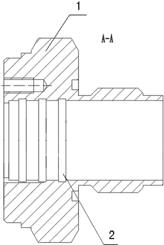
[0024] The fastening connection structure includes a card groove 2 and an outer tube locking notch 3 arranged on the inner wall of the threaded joint cavity, the outer tube W is an aluminum alloy outer tube that can be deformed by extrusion, and the aluminu...

Embodiment 2

[0031] The difference between this embodiment and embodiment 1 is:

[0032] The outer wall of the upper end of the outer tube W is directly welded to the inner wall of the inner cavity of the threaded joint 1 to achieve a firm connection between the outer tube W and the threaded joint 1 .

[0033] The method of connecting and fixing the outer pipe of the liquid level sensor in this embodiment is as follows:

[0034] After the upper end of the aluminum alloy outer tube is inserted into the inner cavity of the threaded joint 1, the outer wall of the upper end of the outer tube W is directly welded to the inner wall of the inner cavity of the threaded joint 1 by means of laser or argon arc welding. Below the threaded opening (not shown in the figure) of the joint 1, so as to facilitate the further assembly of other component structures of the liquid level sensor.

[0035] All the other are with embodiment 1.


PUM


Abstract

The invention provides a liquid level sensor. The liquid level sensor comprises a threaded connector and an outer pipe used as an outer electrode, wherein threads are arranged on the outer wall of the upper end of the threaded connector, the upper end of the outer pipe extends into an inner cavity of the threaded connector, the outer diameter of the outer pipe fits the diameter of the inner cavity of the threaded connector, and the outer wall of the upper end of the outer pipe is directly welded to the inner wall of the inner cavity of the threaded connector, or a fastening and connecting structure is arranged between the outer wall of the upper end of the outer pipe and the inner wall of the inner cavity of the threaded connector. The invention further provides a connecting and fixing method of the outer pipe of the liquid level sensor. The liquid level sensor is simple in structure, the connecting and fixing method of the outer pipe of the liquid level sensor is easy and convenient to operate, and the liquid level sensor is firmly installed so that safety and reliability of the liquid level sensor in the process of actual use can be guaranteed.

Description

technical field [0001] The invention relates to a liquid level sensor and a method for connecting and fixing an outer pipe thereof. Background technique [0002] The liquid level sensor realizes the measurement by collecting the change of the liquid level height, which mainly uses the coverage area of ​​the two electrodes (that is, the outer tube W used as the outer electrode and the inner tube N used as the inner electrode) to change with the change of the liquid level. changes (see figure 1 ), so as to cause the liquid level measurement corresponding to the capacitance change relationship, and convert the capacitance change (that is, the change of the measured liquid level H) into a standard electrical signal output. [0003] At present, the outer tube of the liquid level sensor is connected to the outer wall of the hexagonal thread joint by laser or argon arc welding, and there are obvious welding convex marks and irregular arc lines T at the welding place (see figure 1...

Claims


Application Information

Patent Timeline
Patent Type & Authority Applications(China)
IPC IPC(8): G01F23/00G01F23/26
Inventor 李东海唐乐董安谢功贤
Owner FIRSTRATE SENSOR
Why Eureka
Try Eureka