Optimal design method for internal structure of machine tool body

A technology for optimizing design and internal structure, applied in computing, special data processing applications, instruments, etc., can solve problems such as time-consuming and increase the labor intensity of designers, and achieve the effects of saving time, optimizing target coordination, and reducing labor intensity

Inactive Publication Date: 2014-12-24
XI AN JIAOTONG UNIV
View PDF6 Cites 18 Cited by
  • Summary
  • Abstract
  • Description
  • Claims
  • Application Information

AI Technical Summary

Problems solved by technology

[0003] In order to reduce the quality of the machine bed and improve the rigidity and other performances, the layout, shape and size of the bed ribs are mainly designed. Most designers of machine tool manufacturers use 3D software to build the model of the bed, and constantly modify the structure size of the ribs. Then import the finite element software for calculation, and repeat the above steps to find the optimal size. The optimization results obtained by this optimization method are accidental, and it takes a lot of time, which increases the labor intensity of the designer.

Method used


Image

  • Optimal design method for internal structure of machine tool body
  • Optimal design method for internal structure of machine tool body
  • Optimal design method for internal structure of machine tool body

Examples


Embodiment 1

[0046] The present invention is described by taking the YK series CNC worm gear grinding machine body of a domestic manufacturer as an example, wherein the overall size of the bed is 2500×1250×565mm, the three-dimensional software adopts Pro / e, the topology optimization software adopts Hyperworks, and the finite element software Using Ansys, auxiliary software matlab.

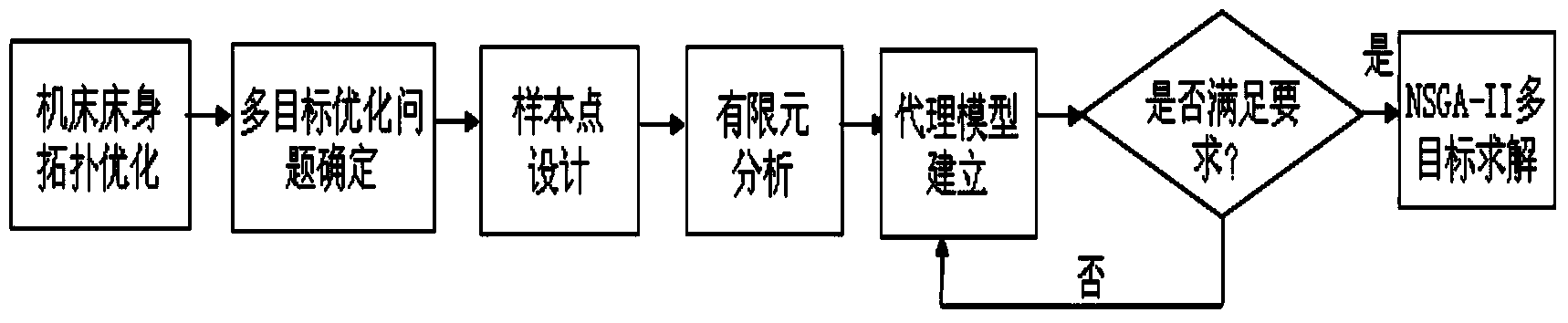
[0047] The topology optimization step of the internal structure of the machine bed includes the following steps:

[0048] a1) Establish the 3D CAD model of the machine bed in the Pro / e software based on the existing bed model or the 2D engineering drawing of the machine bed; use the seamless interface between the Pro / e software and the topology optimization software Hyperworks The 3D CAD model of the machine bed is imported into Hyperworks; the 3D CAD model of the machine bed is divided into a topology optimization area and a non-topology optimization area, and the area outside the bed that has an assembly rela...


PUM


Abstract

The invention discloses an optimal design method for an internal structure of a machine tool body. The optimal design method comprises topological optimization of the internal structure of the machine tool body and multi-objective optimization of thickness and height of a ribbed plate of the machine tool body. The topological optimization of the internal structure of the machine tool body comprises the following steps: establishing a body three-dimensional CAD (Computer Aided Design) model; determining a topological optimization region and a non-topological optimization region; establishing a finite element model of the topological optimization; determining boundary conditions; determining optimization objectives and constraint conditions and establishing a finite element model of the topological optimization; the multi-objective optimization of the thickness and the height of the ribbed plate of the machine tool body comprises the following steps: establishing a parameterized finite element model of the body according to the topological optimization result; designing sample points; determining optimization objectives and constraints; performing finite element analysis at the sample points to extract values of the optimization objectives and the constraints at each sample point; establishing agent models of the optimization objectives and the constraints; solving the multi-objective optimization problem. Through the method, the internal structure of the machine tool body is optimized, and the time is saved.

Description

technical field [0001] The invention relates to an optimization design method, in particular to an optimization design method for the internal structure of a machine bed. Background technique [0002] As the basic support of the machine tool, the bed plays a role in supporting the weight of the machine tool components that have a matching relationship with the upper surface of the bed and the weight of the workpiece to be processed. The deformation of the bed will directly cause the parts supported by the bed to tilt, which will affect the quality of the processed parts. Especially in precision machine tools, the deformation of the bed is more important, so the design of the bed has become a key technology for machine tool manufacturers. At present, a considerable number of machine tool manufacturers still use the traditional experience design and imitation method to design the bed. In order to achieve the expected goal, regardless of the cost, the designed bed also has the ...

Claims


Application Information

Patent Timeline
Patent Type & Authority Applications(China)
IPC IPC(8): G06F17/50
Inventor 王伊卿宋元申周子超王彬洪军卢秉恒
Owner XI AN JIAOTONG UNIV
Why Eureka
Try Eureka