

High voltage ride-through method of wind power converter
A wind power converter, high voltage technology, applied in wind power generation, single grid parallel feeding arrangement, etc., can solve the problems of grid-connected active power DC bus voltage grid electromotive force imbalance, fluctuation and other problems, achieve good control and suppress fluctuations Effect
- Summary
- Abstract
- Description
- Claims
- Application Information
AI Technical Summary
Problems solved by technology
Method used
Image

Examples
Embodiment Construction
[0020] The present invention will be described in further detail below in conjunction with the accompanying drawings.
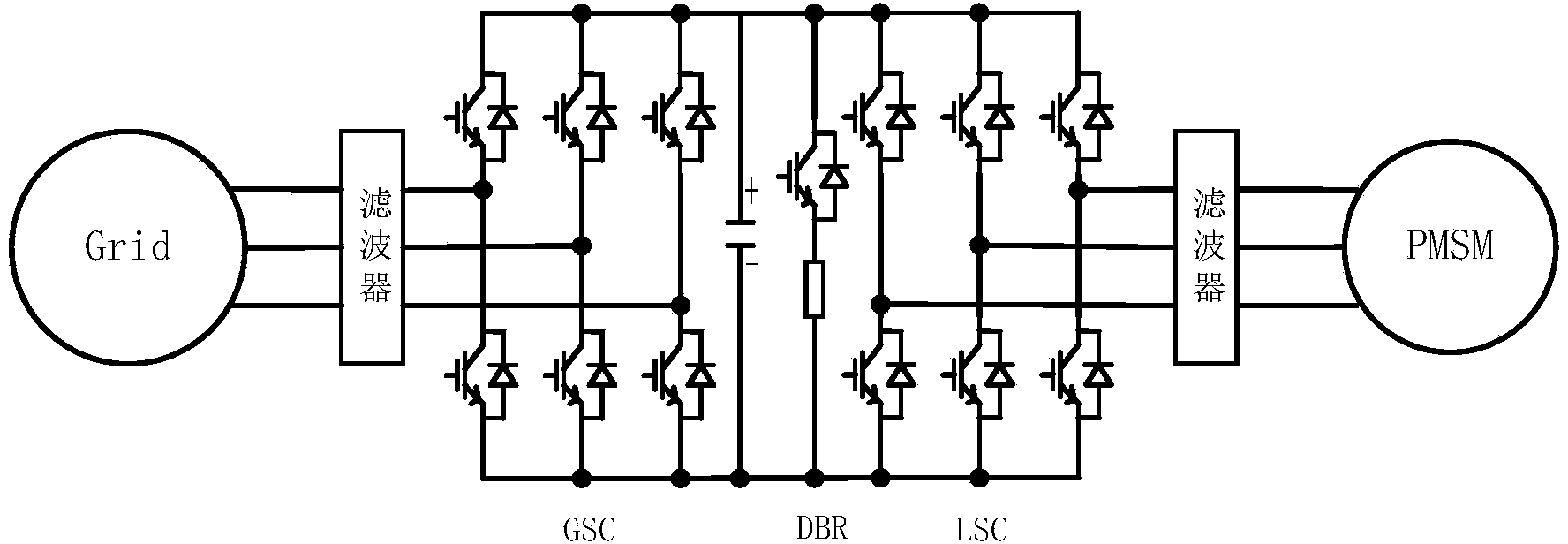
[0021] Such as figure 1 as shown, figure 1 It is a system structure diagram of the present invention, the wind power converter includes a grid-side converter GSC, a machine-side converter LSC, a DC bus voltage discharge circuit DBR, and a DC bus voltage discharge circuit DBR includes an IGBT, a DC discharge resistor R, A diode, the diode is connected in reverse parallel with the IGBT and then connected in series with the DC discharge resistor R.
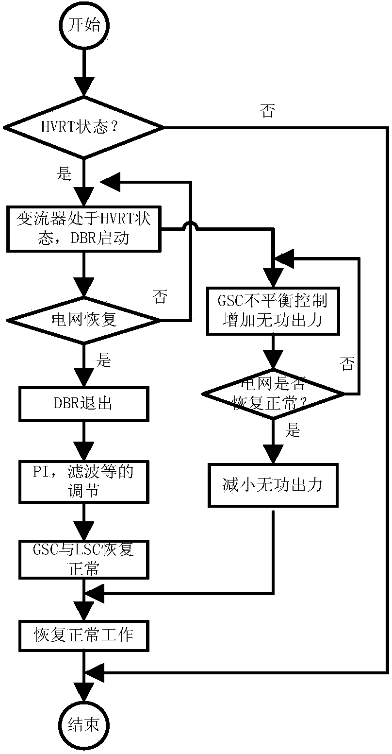
[0022] Real-time monitoring of the grid voltage of the wind turbine generator set, when the detected grid voltage is a set multiple of the rated voltage, here we take 1.1 times as an example. When the detected grid voltage is 1.1 times the rated voltage, the converter enters the high voltage ride-through control state, and the grid-side converter increases the reactive output by changing the reactive current. The ...
PUM
 Abstract
Description
Claims
Application Information