Novel special equipment for demolding resin diamonds

A special equipment and technology of resin drill, which is applied in the field of resin drill processing, can solve the problems of uneven appearance, unsatisfactory effect and high cost of silicone molds of resin drills, so as to prevent artificial damage to molds and products, reduce manual operation costs, and save labor cost effect

Active Publication Date: 2015-01-07
HENAN INST OF SCI & TECH
View PDF5 Cites 5 Cited by
  • Summary
  • Abstract
  • Description
  • Claims
  • Application Information

AI Technical Summary

Problems solved by technology

[0003] The existing method of removing resin diamonds from the mold is to shake them out by hand or one by one, or use a dehairing machine with a glue stick to rub them repeatedly in a vertical drum, which can easily lead to The rubber block is torn and rotted after being hit, and cannot be used any longer. The reuse rate is low, the operation efficiency is low, the labor intensity is high, and the cost of the silicone mold is high, which reduces the yield. Severe wear, low transparency, poor reflective effect, seriously affect the sales price
[0004] The post-research design used various technical solutions such as scraper blades on scraper rollers and high-speed rotating and rolling brushes to separate resin drills, but the results were not ideal. After practice tests, it was shown that the structure of brushes and scraper blades was used to reduce the impact of resin drills on silicone molds. Hole damage is relatively large, and the appearance of the resin drill produced by the damaged silicone mold is uneven, the edges and corners are not clear, the reflection is poor, and the transparency is low, causing great trouble to the subsequent repeated use of the silicone mold, and the cost is too high

Method used


Image

  • Novel special equipment for demolding resin diamonds
  • Novel special equipment for demolding resin diamonds
  • Novel special equipment for demolding resin diamonds

Examples


Embodiment Construction

[0024] In order to make the object, technical solution and advantages of the present invention clearer, the present invention will be further described in detail below in conjunction with the accompanying drawings and embodiments. It should be understood that the specific embodiments described here are only used to explain the present invention, not to limit the present invention.

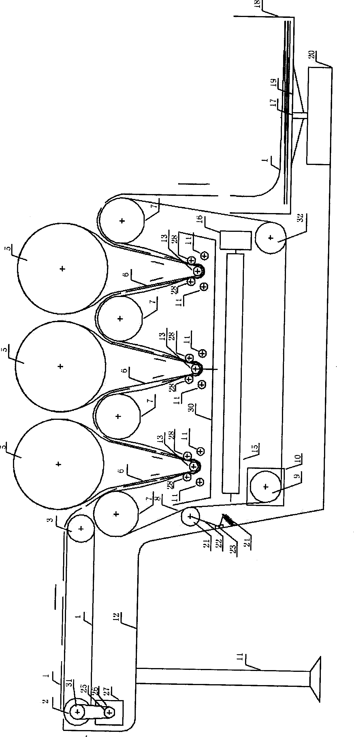
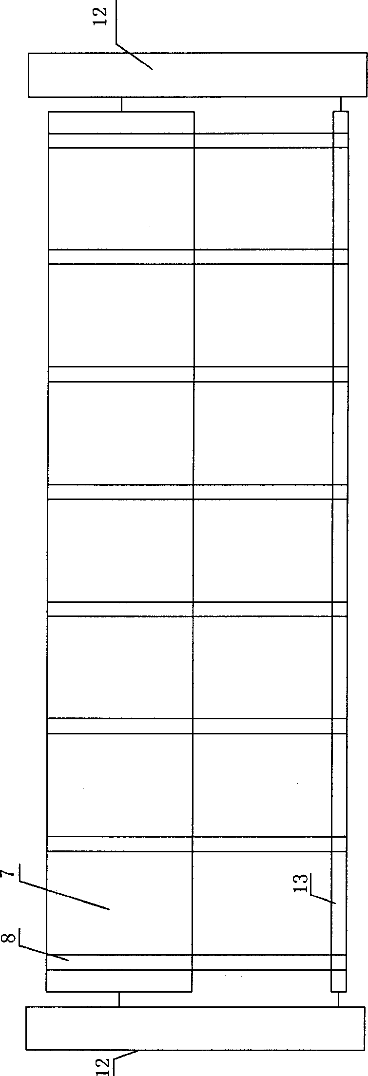
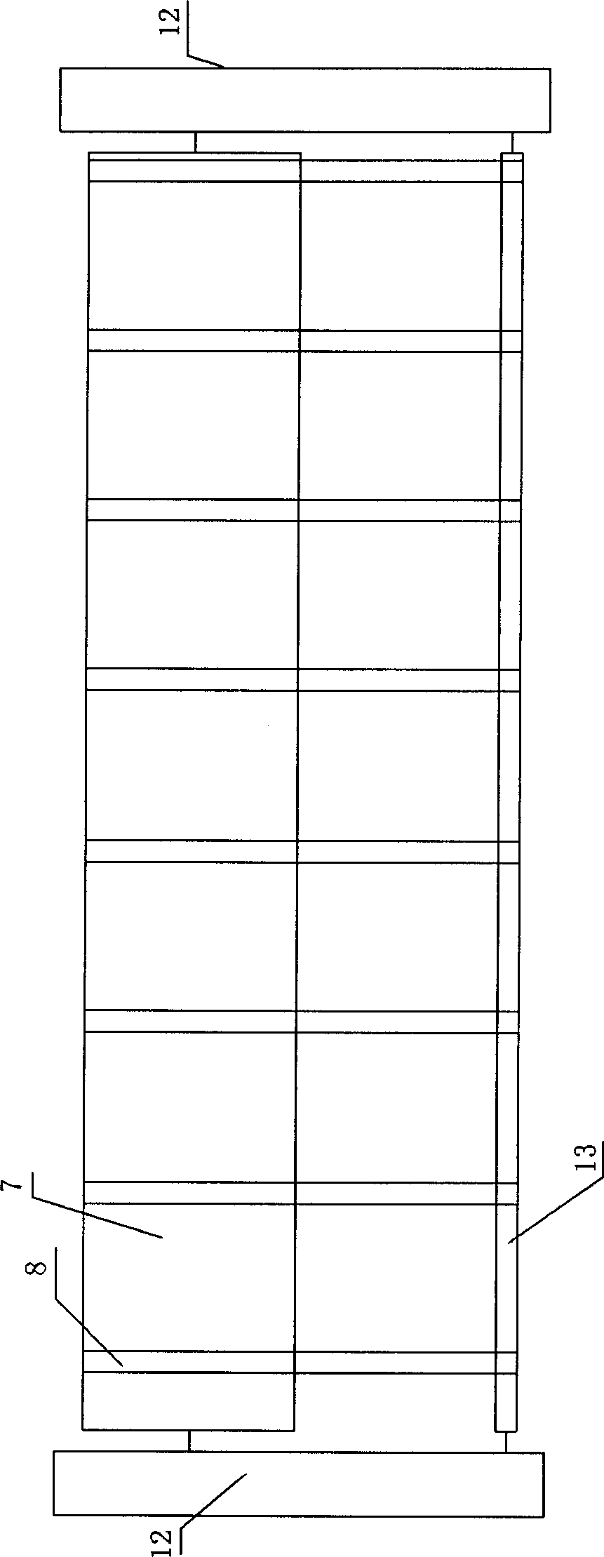
[0025] see Figure 1-4 , a new type of special equipment for resin drill demoulding of the present invention, which demoulds the resin drill 29 in the flat silicone mold 1, including: frame 12, a feeding transmission mechanism arranged on the frame 12, a silicone mold Deformation mechanism, resin drill and discharge mechanism, silicone mold recovery mechanism;

[0026] This feeding conveying mechanism comprises: speed-regulating decelerating motor 27, the main belt pulley 25 that is connected with this speed-regulating decelerating motor 27 coaxial rotations, from belt pulley 31, is connected in t...


PUM


Abstract

The invention relates to the processing field of resin diamonds, in particular to novel special equipment for demolding resin diamonds. A feeding conveying mechanism is used for conveying a silicone mold with a resin diamond, a silicone mold deformation mechanism is used for demolding so that the resin diamond can be taken out of a mold hole of the silicone mold rapidly, demolding is operated repeatedly layer by layer, no missing is caused and the efficiency is high; and then, a resin diamond discharging mechanism is used for automatically collecting the demolded resin diamonds, the mold hole can be effectively prevented from being damaged and deformed, the bottoms of the produced flat-base resin diamond are flat and can be coated conveniently, industrial automatic operation can be carried out, the manual operation cost is greatly reduced, the molds and the products can be prevented from being damaged by humans, and the interference of outside adverse factors is reduced; besides, a silicone mold recovery mechanism is used for automatically collecting the silicone molds, therefore, the silicone mold can be utilized repeatedly and circularly; when the silicone molds are used again, residues and attached resin diamonds in the mold holes do not need to be cleaned again, the period is shortened, the production efficiency is improved and the labor cost is lowered.

Description

technical field [0001] The invention relates to the field of resin drill processing, in particular to a new type of special equipment for resin drill demoulding. Background technique [0002] Resin drill is a kind of decoration made of synthetic resin. The preparation process is generally as follows: firstly, the silicone mold is made by the mold seeding, then the resin is injected into the mold hole of the silicone mold, and after curing, diamond blanks with different shapes and structures are made, and then silver is plated on the bottom to make the bottom refract The light that comes out looks like a diamond sparkle on the front. If you add different additives, you can change the physical properties of the resin drill, such as increasing the hardness, increasing the light transmittance and so on. [0003] The existing method of removing resin diamonds from the mold is to shake them out by hand or one by one, or use a dehairing machine with a glue stick to rub them repea...

Claims


Application Information

Patent Timeline
IPC IPC(8): B29C39/22B29C39/36
Inventor 李勇峰张烨赵利敏郑丽媛郭竞杰张纪梁孙奇勋
Owner HENAN INST OF SCI & TECH
Why Eureka
Try Eureka