
Broadband infrared scanning beam split device and calibrating method

An infrared scanning and spectroscopic device technology, which is applied in the field of infrared radiation spectroscopic testing, can solve the problems of high cost, difficulty in universal adoption, and difficult coating technology of CVF devices.

Inactive Publication Date: 2015-01-07
CHINA ELECTRONIS TECH INSTR CO LTD
View PDF3 Cites 6 Cited by
  • Summary
  • Abstract
  • Description
  • Claims
  • Application Information

AI Technical Summary

Problems solved by technology

The existing technology adopts the CVF spectroscopic method, and the CVF device coating technology is difficult and costly, and it is difficult to be widely used.

Method used


Image

  • Broadband infrared scanning beam split device and calibrating method
  • Broadband infrared scanning beam split device and calibrating method
  • Broadband infrared scanning beam split device and calibrating method

Examples


Embodiment 1

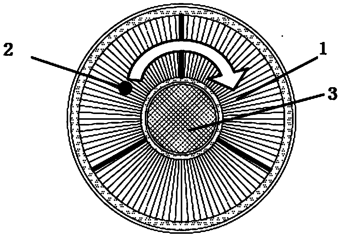
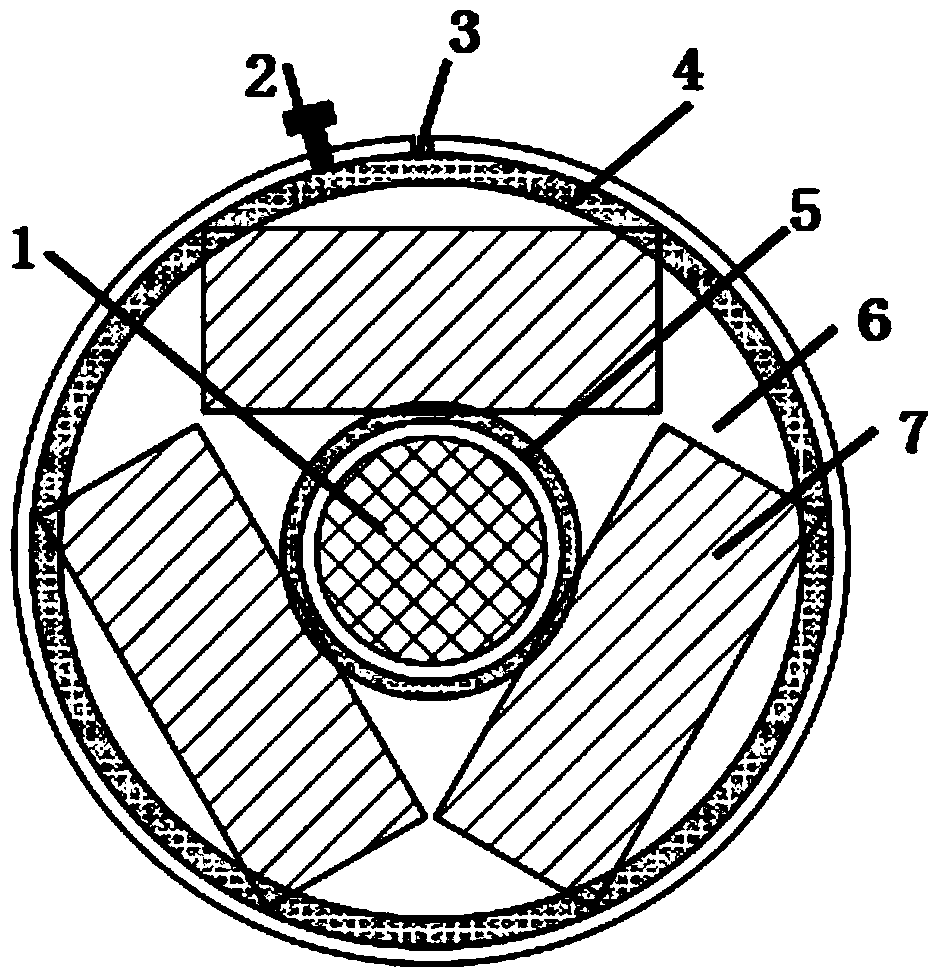
[0030] The present invention designs a device that uses multi-chip combined LVF (strip-shaped gradient filter) for infrared spectrum radiation splitting and can perform high-speed scanning. Such as figure 2 As shown, the device of the present invention includes LVF7, fixture 6, driving motor 1, photoelectric switch 2, zero opening 3, outer pressure ring 4 and inner pressure ring 5, and the driving motor 1 drives the fixture 6 equipped with LVF7 to perform a rotation scanning test. The inner pressure ring 5 and the outer pressure ring 4 just press the non-working area of ​​the LVF7 for fixing, the assembly is simple and firm, and high-speed rotating scanning test can be realized.

[0031] During the test, the light spot converged by the incident lens is hit on the LVF7, and the fixture 6 equipped with the LVF7 is rotated under the drive of the drive motor 1, and the transmitted radiation is detected by an infrared detector, and the scanning is completed with the rotation of th...

Embodiment 2

[0033] On the basis of the above embodiments, the present invention also provides a calibration method for a broadband infrared scanning spectroscopic device,

[0034] Compared with using CVF for scanning and splitting, the present invention greatly reduces the difficulty of coating technology and the cost of coating. Aiming at the wavelength inhomogeneity in the LVF scanning process, a corresponding wavelength calibration algorithm is designed to realize continuous scanning of wide infrared band spectral radiation.

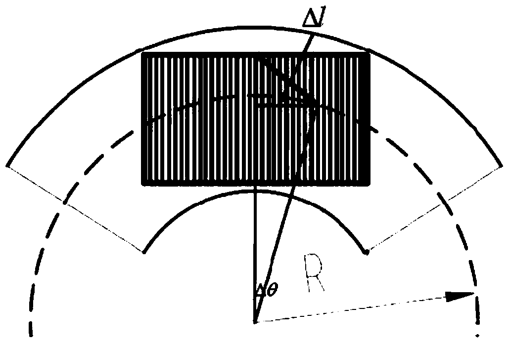
[0035] Since the use of LVF for light splitting is not as uniform as CVF, there will be invalid data in the test using the above device. For this, a corresponding wavelength calibration method using the above device is designed to establish the corresponding relationship between wavelength and intensity. In order to achieve wide Continuous testing of spectral radiation in the infrared band, such as image 3 Shown:

[0036] Since the filter is scanned at a unifor...


PUM


Abstract

The invention provides a broadband infrared scanning beam split device and a calibrating method. The device comprises an LVF, a clamp, a drive motor, a photoelectric switch, a zero position opening, an external pressing ring and an internal pressing ring. The drive motor drives the clamp with a gradual optical filter to conduct rotating scanning test, the internal pressing ring and the external pressing ring of the clamp press the non-working region of the LVF to conduct fixing, assembly is simple and firm, and the high-speed rotating scanning test can be achieved. Compared with a CVF, by the adoption of the scheme, the coating technology difficulty and coating cost are lowered greatly, and through a corresponding wavelength calibrating algorithm, continuous test of broadband infrared radiation can be achieved.

Description

technical field [0001] The invention belongs to the technical field of infrared radiation spectroscopic testing, and in particular relates to a wide-band infrared scanning spectroscopic device and a calibration method. Background technique [0002] Infrared gradient filter is mainly used in the infrared spectrum radiation test. It transmits radiation of different wavelengths at different positions and is used as a spectroscopic device. In the application, it is required to cover two infrared atmospheric windows of 3-5 μm and 8-14 μm, and can perform Fast wavelength scanning, based on the characteristics of coating technology (the maximum wavelength is not greater than twice the minimum wavelength), is currently generally implemented by splicing 3 to 4 CVFs (circular gradient filters) into a circular ring for rotational scanning. However, due to the difficulty of CVF coating technology (there is no mature corresponding coating technology in our country), the high cost limits ...

Claims


Application Information

Patent Timeline
Patent Type & Authority Applications(China)
IPC IPC(8): G01J3/06
Inventor 胡德信韩顺利侯喜报
Owner CHINA ELECTRONIS TECH INSTR CO LTD
Learn More