Automatic storage battery charging-discharging and capacity detection device

A capacity detection and storage battery technology, applied in measuring devices, measuring electrical variables, measuring electricity, etc., can solve the problems of slow frequency response, poor anti-interference ability, and high cost, achieve fast frequency response, meet high-current discharge, Simple effect of power supply circuit

Active Publication Date: 2015-01-07
JIANGSU YINJIA GROUP
View PDF10 Cites 9 Cited by
  • Summary
  • Abstract
  • Description
  • Claims
  • Application Information

AI Technical Summary

Problems solved by technology

However, the existing several types of charging and discharging devices require too many manual operations, the stability of the discharge current is not good, and improper operation will cause damage to the battery, which is difficult to meet the needs of the future market.
[0003] The battery charging and discharging device in the prior art often has a complex structure and requires manual operation to realize the charging and discharging function of the battery, which has poor anti-interference ability and high cost
In the control process of charge and discharge, there is also a lack of visual observation means, so that users cannot clearly understand the relevant graphics and curves of battery performance.
[0004] In the prior art, the problem of output current accuracy cannot be solved, and the frequency response speed is slow, which cannot satisfy large current discharge, and red hot phenomenon is easy to occur during the discharge process, and the safety is low
[0005] The battery charging and discharging device in the prior art cannot artificially control parameters such as the discharge current and the number of discharges, and the operation is not convenient and flexible enough.

Method used


Image

  • Automatic storage battery charging-discharging and capacity detection device
  • Automatic storage battery charging-discharging and capacity detection device
  • Automatic storage battery charging-discharging and capacity detection device

Examples


Embodiment Construction

[0030] Below in conjunction with accompanying drawing, technical scheme of the present invention is described in further detail:

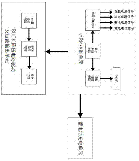
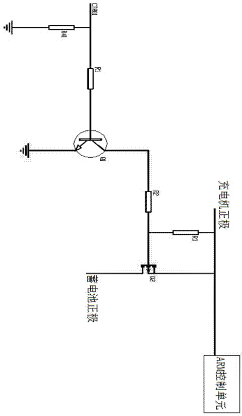
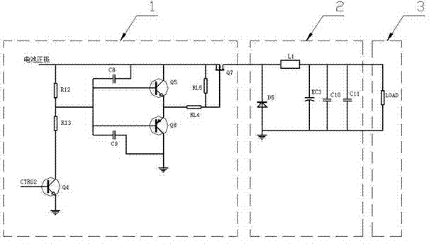
[0031] The schematic diagram of the module structure of the present invention is as figure 1 As shown, the battery automatic charging and discharging and capacity detection device includes an ARM control unit, a battery charging unit, a BUCK step-down circuit drive and a constant current output unit, and the output terminals of the ARM control unit are respectively connected to the battery charging unit, the BUCK step-down circuit The voltage circuit drive and the constant current output unit are connected, wherein the ARM control unit is composed of a signal acquisition circuit, an ARM minimum system circuit, a communication control circuit and a host computer connected in sequence; the signal acquisition circuit includes a charging current detection circuit, a discharge current A detection circuit, a battery voltage detection circuit and a load d...


PUM


Abstract

The invention discloses an automatic storage battery charging-discharging and capacity detection device which comprises an ARM control unit, a storage battery charging unit and a BUCK step-down circuit drive and constant current output unit. The output end of the ARM control unit is connected with the storage battery charging unit and the BUCK step-down circuit drive and constant current output unit; the ARM control unit is formed by a signal acquisition circuit, an ARM minimum system circuit, a communication control circuit and an upper computer, and the signal acquisition circuit, the ARM minimum system circuit, the communication control circuit and the upper computer are connected in sequence; the storage battery charging unit comprises a charger, a storage battery and a corresponding charging control circuit, the positive electrode of the charger is connected with the power supply positive electrode of the ARM control unit, and power supply to the ARM control unit is achieved; the BUCK step-down circuit drive and constant current output unit comprises an MOS drive circuit, a BUCK step-down circuit and a discharging load resistor. The automatic storage battery charging-discharging and capacity detection device is simple in structure and high in anti-jamming capability and has application and popularization value, and the storage battery is automatically charged and discharged without manual operation.

Description

technical field [0001] The invention discloses a storage battery automatic charge and discharge and capacity detection device, in particular to a charge and discharge control device which adjusts a pulse width modulation signal in real time to drive a BUCK chopper circuit to output a constant current, and relates to the field of storage battery detection. Background technique [0002] As a very common chemical power source in the industrial field, the battery's working stability and safety are extremely important. However, the existing charging and discharging devices require too many manual operations, poor discharge current stability, and improper operation will cause damage to the storage battery, making it difficult to meet the future market demand. [0003] The battery charging and discharging device in the prior art often has a complicated structure, requires manual operation to realize the charging and discharging function of the battery, has poor anti-interference ab...

Claims


Application Information

Patent Timeline
Patent Type & Authority Applications(China)
IPC IPC(8): G01R31/36
Inventor 姚平朱忠伟檀三强
Owner JIANGSU YINJIA GROUP
Why Eureka
Try Eureka