Passive suppression method for conducted electromagnetic interface of PWM (power width modulation) power converter

A technology for conducting electromagnetic interference and power converters, which is applied to output power conversion devices, electrical components, etc., can solve the problems of reduced reliability of motor drive systems, increased failure rates, and failure to meet electromagnetic compatibility standards, and achieves suppression of conducted electromagnetic interference. Interfere, remove negative effects

Inactive Publication Date: 2015-01-07
HARBIN UNIV OF SCI & TECH
View PDF4 Cites 15 Cited by
  • Summary
  • Abstract
  • Description
  • Claims
  • Application Information

AI Technical Summary

Problems solved by technology

[0007] The purpose of the present invention is to solve the problem that the existing electromagnetic interference affects the reliability of the motor drive system, the reliability decreases, the failure rate increases, and the electromagnetic compatibility standard cannot be reached, and a passive suppression method for the conduction electromagnetic interference of the PWM power converter is provided.

Method used


Image

  • Passive suppression method for conducted electromagnetic interface of PWM (power width modulation) power converter
  • Passive suppression method for conducted electromagnetic interface of PWM (power width modulation) power converter
  • Passive suppression method for conducted electromagnetic interface of PWM (power width modulation) power converter

Examples


specific Embodiment approach 1

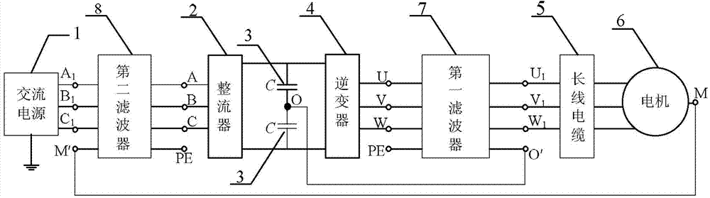
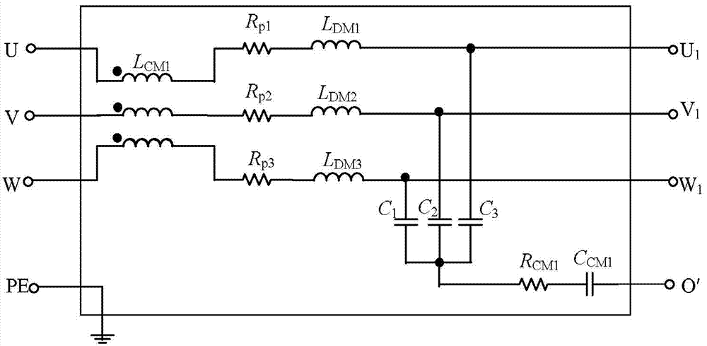
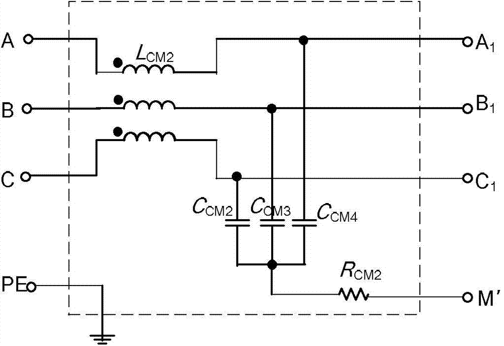
[0033] Specific implementation mode one: the following combination Figure 1-Figure 3 , Figure 6-Figure 10 Describe this embodiment, the PWM power converter conduction electromagnetic interference passive suppression method described in this embodiment, the suppression method is to use two filter topology to connect to the PWM power converter, the filter topology design process is:

[0034] Step 1, using a receiver to measure the conduction interference of the PWM power converter to obtain an electromagnetic interference spectrum, the electromagnetic interference spectrum includes a common-mode interference spectrum and a differential-mode interference spectrum;

[0035] Step 2, subtracting the common-mode interference spectrum and the differential-mode interference spectrum from the conducted interference emission limit curve of the PWM power converter, respectively, to obtain the common-mode spectrum and differential-mode spectrum attenuated by the filter;

[0036] Step 3,...

specific Embodiment approach 2

[0040] Specific implementation mode two: the following combination figure 2 Describe this embodiment, this embodiment will further explain Embodiment 1, the corner frequency f of differential mode noise and common mode noise described in step 3 CM for:

[0041] Among them: A Cnoise Indicates the maximum magnitude of attenuation, F 0 Indicates the frequency at the magnitude.

specific Embodiment approach 3

[0042] Specific implementation mode three: the following combination figure 2 Describe this implementation mode, this implementation mode will further explain the implementation mode 1, the specific process of obtaining the parameter value of the common mode inductance described in step 4 is:

[0043] Step 41. According to Faraday's law of electromagnetic induction, the inductance flux Φ and the common-mode voltage U CM The relationship is:

[0044] Among them: N represents the number of turns of the inductance coil;

[0045] Step 42. Obtain the magnetic flux density B as:

[0046] Among them: S represents the effective cross-sectional area of ​​the inductor coil core;

[0047] Step 43: Obtain the common mode inductance value L CM for:

[0048] Among them: l represents the average length of the magnetic circuit of the inductance coil core, μ represents the magnetic permeability of the inductance coil core.

[0049] In this embodiment, the main consideration for t...


PUM


Abstract

The invention discloses a passive suppression method for the conducted electromagnetic interface of a PWM (power width modulation) power converter, belongs to the field of motor drive control and electromagnetic compatibility of integrated motor systems, and aims to solve the problems of low reliability, increase of a failure rate and incapability of reaching an electromagnetic compatibility standard of the conventional motor driving system under the influence of electromagnetic interface. An alternating current power supply, a rectifier, two direct current bus capacitors, an inverter, a long cable, a motor, a first filter and a second filter are involved, wherein the alternating current power supply is connected with the rectifier; the output end of the rectifier is connected with the two direct current bus capacitors; the other ends of the direct current bus capacitors are connected with the inverter; the output of the inverter is connected to the motor through the long cable; the input end of the first filter is connected to the inverter, a part of the output end of the first filter is connected to the motor, and another terminal is led from the output end of the first filter to be connected to a direct current bus clamping neutral point; the input end of the second filter is connected to the rectifier, a part of the output end of the second filter is connected to a power grid, and another terminal is led from the output end of the second filter to be connected to a neutral point of the motor. The method is applied to a PWM motor driving device.

Description

technical field [0001] The invention belongs to the field of motor drive control and electromagnetic compatibility of an integrated motor system. Background technique [0002] Power electronic equipment is more and more widely used in industry and people's life. Although it has shown great advantages in energy saving, improving the degree of industrial automation and human living environment, etc., because power electronic equipment relies on electromagnetic energy to carry out Work, some useful or useless electromagnetic energy is emitted when they are running, forming electromagnetic interference and affecting the normal work of other devices in the system. Therefore, with the development of power electronics technology, the problem of electromagnetic compatibility has become increasingly prominent. [0003] According to the description of the definition of electromagnetic compatibility in GJB72-1985 "Terms of Electromagnetic Interference and Electromagnetic Compatibility...

Claims


Application Information

Patent Timeline
Patent Type & Authority Applications(China)
IPC IPC(8): H02M1/44
CPCH02M1/44
Inventor 肖芳戈宝军陶大军王雪健
Owner HARBIN UNIV OF SCI & TECH
Why Eureka
Try Eureka