
Settler-free gas-solid separation method and equipment

A gas-solid separation, non-settling technology, applied in the field of fluidization and petrochemical industry, can solve the problems of poor feeding leg of the secondary separator, catalyst loss, unfavorable flow of fine powder, etc., to reduce excessive oil and gas. Thermal cracking reaction, reduced dry gas yield, and smooth discharge

Inactive Publication Date: 2015-01-14
刘英聚
View PDF4 Cites 3 Cited by
  • Summary
  • Abstract
  • Description
  • Claims
  • Application Information

AI Technical Summary

Problems solved by technology

In this scheme, the material leg of the secondary separator adopts a folded tube structure, which is not conducive to the flow of fine powder, and the wing valve placed in the stripping section is easily buried by the catalyst, resulting in poor feeding of the material leg of the secondary separator and a large amount of catalyst loss.

Method used


Image

  • Settler-free gas-solid separation method and equipment
  • Settler-free gas-solid separation method and equipment
  • Settler-free gas-solid separation method and equipment

Examples


Embodiment Construction

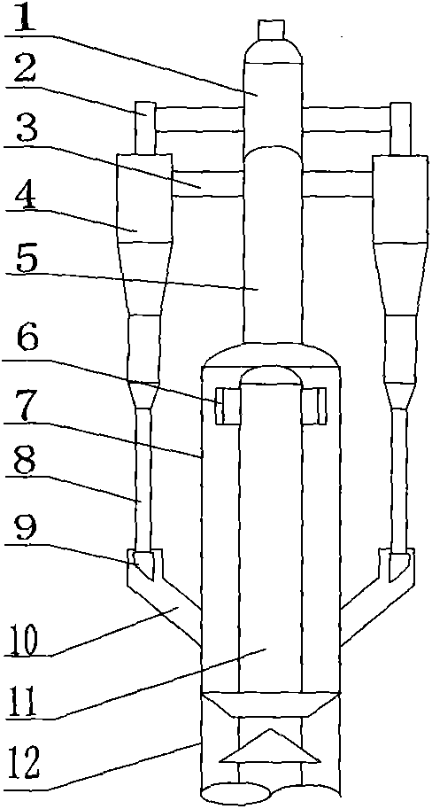
[0023] See figure 1 , the outlet of the riser 11 is connected to the cyclone 6, and the outer side of the cyclone 6 is provided with a sealing cover 7. The sealing cover 7 adopts a straight cylinder structure, the lower end of the sealing cover 7 is connected with the stripping section 12, and the upper end is connected with the secondary separator 4 through the sealing cover exhaust pipe 5 and the secondary inlet pipe 3. The upper end of the secondary separator 4 is connected to the outlet main pipe 1 through the secondary exhaust pipe 2, and the lower end is connected to the material leg 8 and the wing valve 9. The lower end of the catalyst guide pipe 10 is connected to the lower part of the sealing cover 7 , and the upper end wraps the wing valve 9 .

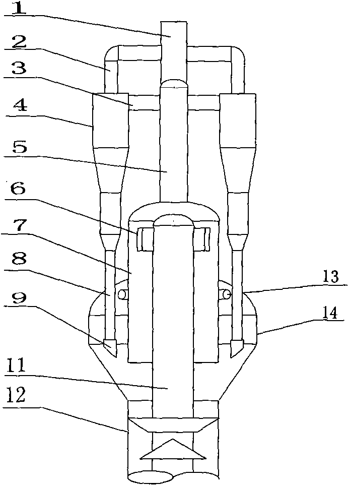
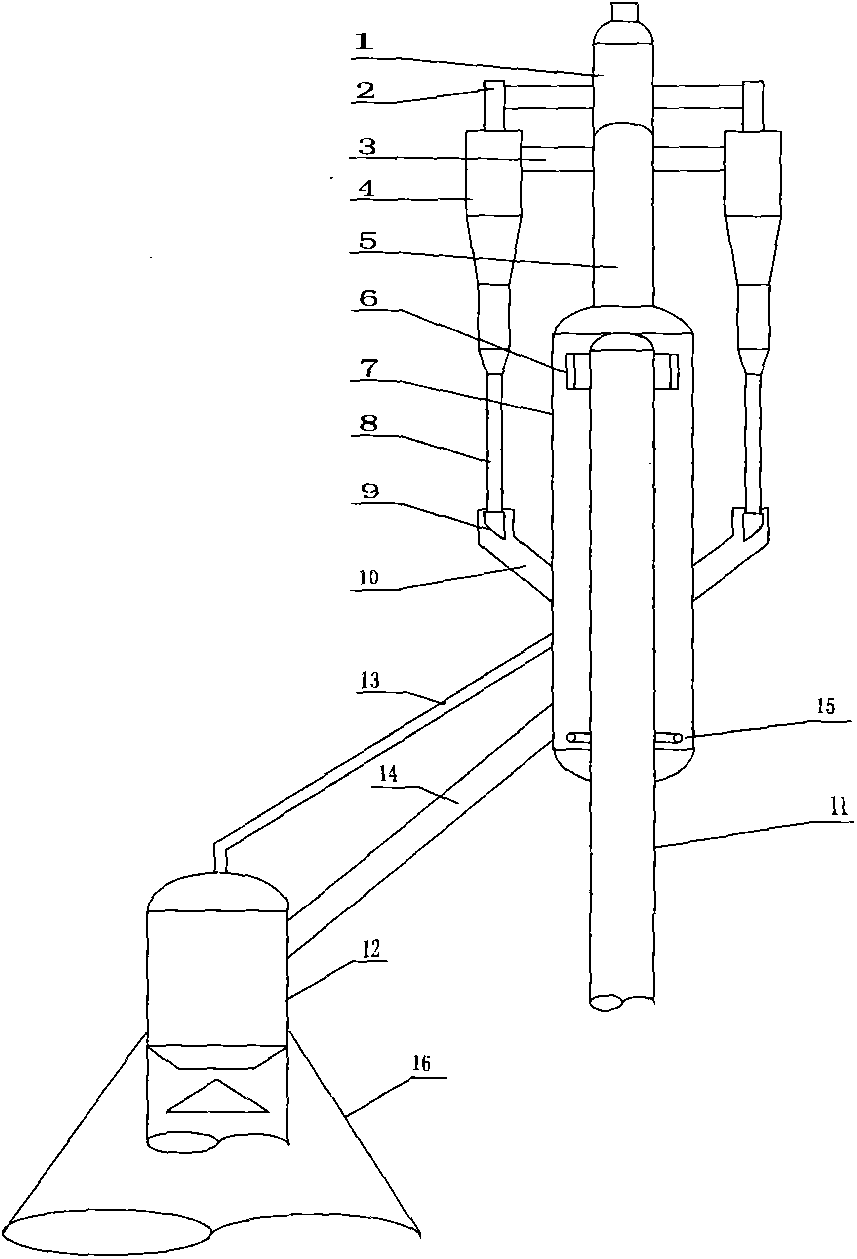
[0024] See figure 2 , There is a remodeling plan for the parallel device of the settler, the outlet of the riser 11 is connected with the cyclone 6, and the outer side of the cyclone 6 is provided with a sealing cover 7. ...


PUM


Abstract

The invention relates to a settler-free gas-solid separation method and belongs to the technical field of petrochemical engineering and fluidization. The method is used for solving the problems of reaction that settlers undergo coking and excessive oil vapor thermal cracking. The method comprises the processes of rapid gas-solid separation, second-stage separation, dipleg flutter valve discharge and oil vapor lead-out and is characterized in that due to a settler-free design, closed rapid cyclone separation is adopted to be mated with second-stage cyclone separation, catalyst diversion facilities are arranged, the catalyst diversion facilities are connected with the rapid cyclone separation and the second-stage separation, so as to form a closed separation system, and a catalyst and oil vapor, which are discharged from second-stage flutter valves, are closely guided to the closed separation system. The method has the advantages that the coking of the settlers is eliminated; due to closed rapid cyclone separation, the gas-solid separation efficiency reaches over 98%, and the retention time of the oil vapor is shorter than 5 seconds, so that the reaction of excessive thermal cracking of the oil vapor is obviously reduced, the yield of dry gas is lowered, and the yield of products is increased; the discharging of diplegs is smooth, so that blow-by is avoided; the equipment maintenance is facilitated, and the equipment investment is greatly reduced. The invention further provides an external closed rapid cyclone separator, an external second-stage separator and external catalyst diversion equipment, which are used for implementing the method disclosed by the invention. The method and equipment are applied to devices for catalytic cracking, catalytic pyrolysis and the like.

Description

technical field [0001] The invention belongs to the technical fields of petrochemical industry and fluidization, and in particular relates to a gas-solid separation method and equipment without a settler. Background technique [0002] The outlet of the riser reactor of the catalytic cracking unit in the refinery is equipped with a gas-solid rapid separation device, which is used to realize the rapid separation of oil gas and catalyst and terminate the cracking reaction. In the early days, there were umbrella caps, inverted L, T-shaped and other structural types, and the separation efficiency was generally 70% to 80%. The separated oil and gas rose slowly in the larger-diameter settler, and then entered the secondary separator at the top of the settler. This part of oil and gas stays in the settler for 20 to 50 seconds, and there are still reactions such as excessive thermal cracking and condensation at a high temperature of 500°C, which affects the yield of light oil, and ev...

Claims


Application Information

Patent Timeline
IPC IPC(8): B01D45/12C10G11/18
CPCB01D45/12C10G11/18
Inventor 刘英聚
Owner 刘英聚
Learn More