
Directly water-cooled rectangular planar target structure

A flat target and rectangular target technology, applied in the field of rectangular flat target and rectangular flat target structure, can solve the problem of affecting the effective utilization area of ​​the target and the power of the target, the target and the magnetic assembly being fixed, and affecting the sputtering power supply of the target. Power and other issues, to achieve the effect of large-area uniform and rapid deposition of thin films, improving target utilization, and expanding uniform sputtering area

Inactive Publication Date: 2015-01-14
苏州求是真空电子有限公司
View PDF5 Cites 0 Cited by
  • Summary
  • Abstract
  • Description
  • Claims
  • Application Information

AI Technical Summary

Problems solved by technology

However, in practical applications, the traditional rectangular planar target has two major defects. One is that the target and the magnetic assembly are fixed, resulting in the inability of the magnetic field to be uniformly distributed on the rectangular target surface, and V is prone to occur during sputtering etching. shaped etching groove, so that the utilization rate of the target is low; the second is that the cooling of the target is indirect, that is, there is a metal layer between the target and the cooling water for electrical and thermal conduction, and for the metal layer and the The close contact between the targets also needs to be coated with a layer of heat-conducting silicone grease and other materials, which affects the cooling of the target, and then affects the increase in the power of the sputtering power applied to the target
The above defects affect the effective use area and target power of the target, so it is urgent to improve

Method used


Image

  • Directly water-cooled rectangular planar target structure
  • Directly water-cooled rectangular planar target structure

Examples


Embodiment Construction

[0018] The present invention will be specifically introduced below in conjunction with the accompanying drawings and specific embodiments.

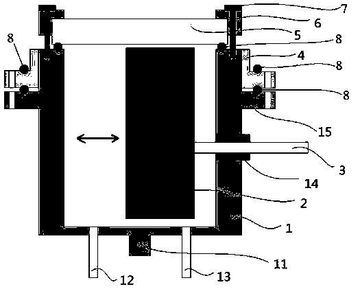
[0019] see figure 1 , a direct water-cooled rectangular planar target structure of the present invention generally includes three major components: a cooling pool 1 , a magnetic assembly 2 and a rectangular target 5 .

[0020] Wherein, the cooling pool 1 is used to accommodate cooling water, preferably made of metal copper or copper alloy, at the bottom end away from the open end is provided with: a cathode electrode 11, a cooling water inlet pipe 12 and a cooling water outlet pipe 13, generally That is, the cathode electrode 11 is arranged in the middle of the cooling water inlet pipe 12 and the cooling water outlet pipe 13, and can be fixed on the cooling pool 1 by means of screws or the like. Of course, the installation positions of the cooling water inlet pipe 12 and the cooling water outlet pipe 13 are not limited to this, as long a...


PUM


Abstract

The invention discloses a directly water-cooled rectangular planar target structure, which comprises a cooling pool, a magnetic assembly and a rectangular target, wherein the rectangular target is tightly arranged at an opening end of the cooling pool, the magnetic assembly is arranged in the cooling pool and can do reciprocating motion along the direction of a plane in which the rectangular target is; and a cathode electrode, a cooling water inlet pipe and a cooling water outlet pipe are arranged at the bottom end, far away from the opening end, of the cooling pool. The directly water-cooled rectangular planar target structure has the beneficial effects that the magnetic assembly does reciprocating motion in the cooling pool, so that a horizontal magnetic field is uniformly distributed on the target plane; and by adopting brand-new magnetic steel arrangement design, the range of the uniform magnetic field is extended to the outer side of the maximum translation position of the magnetic assembly, so that the uniform sputtering area is increased, and the effective utilization of a target material is improved. In addition, the cooling water is directly contacted with the target material, cooling is more direct, so that the heat conducting efficiency of the target material is improved, the power of the target material can be further enhanced, and the large-area uniform and fast deposited film can be realized.

Description

technical field [0001] The invention relates to a rectangular planar target, in particular to a direct water-cooled rectangular planar target structure, and belongs to the technical field of magnetron sputtering coating. Background technique [0002] The magnetron sputtering device has the advantages of fast coating rate, low temperature deposition, and no pollution, and has been widely used in various electronic and decorative coating fields. Among all kinds of target materials, the rectangular planar target is widely used because the target material is relatively easy to manufacture. However, in practical applications, the traditional rectangular planar target has two major defects. One is that the target and the magnetic assembly are fixed, resulting in the inability of the magnetic field to be uniformly distributed on the rectangular target surface, and V is prone to occur during sputtering etching. shaped etching groove, so that the utilization rate of the target is lo...

Claims


Application Information

Patent Timeline
Patent Type & Authority Applications(China)
IPC IPC(8): C23C14/35
CPCC23C14/35C23C14/3407
Inventor 冯斌金浩王德苗李东滨
Owner 苏州求是真空电子有限公司
Learn More