
Temporary support bracket for automatic laying and stepping of fully mechanized excavation face

A technology of temporary support and fully mechanized excavation face, which is applied in the direction of mine roof support, shaft lining, tunnel lining, etc., can solve the problems such as the inability to give full play to the efficiency of high-performance roadheaders, the loss of gangue from the roof, and the simultaneous progress, etc. The effect of driving speed and work efficiency, reducing repeated support, and high adaptability

Active Publication Date: 2017-04-05
TAIYUAN INST OF CHINA COAL TECH & ENG GROUP +1
View PDF8 Cites 0 Cited by
  • Summary
  • Abstract
  • Description
  • Claims
  • Application Information

AI Technical Summary

Problems solved by technology

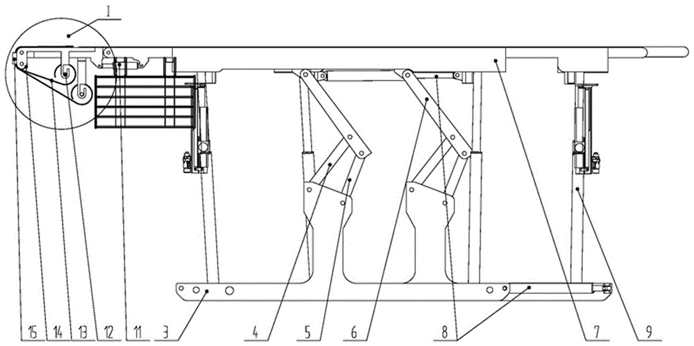
[0004] The present invention solves the problem that during the excavation process of the underground roadway, since the roof cannot be effectively supported in time after the roadway is excavated, accidents of roof falling off and hurting people are often caused, and the synchronous progress of excavation, temporary support and anchor protection cannot be realized, and the full use of To solve the problem of the efficiency of high-performance roadheaders, a temporary support bracket for automatic laying and stepping of fully mechanized excavation faces is provided

Method used


Image

  • Temporary support bracket for automatic laying and stepping of fully mechanized excavation face
  • Temporary support bracket for automatic laying and stepping of fully mechanized excavation face
  • Temporary support bracket for automatic laying and stepping of fully mechanized excavation face

Examples


Embodiment Construction

[0026] The specific embodiment of the present invention will be further described in conjunction with the accompanying drawings.

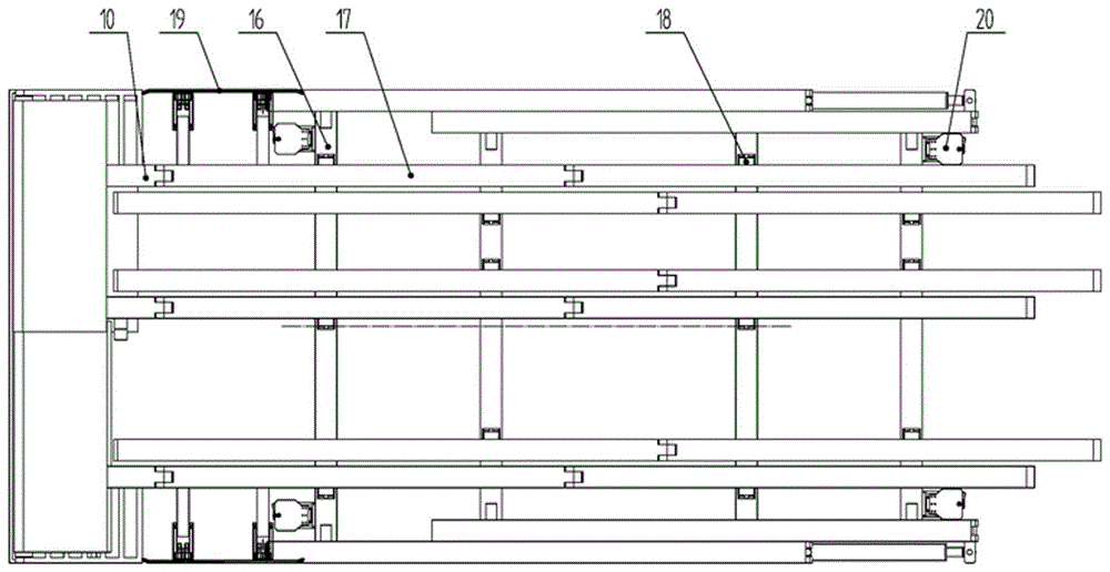
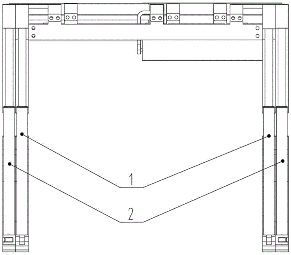
[0027] The automatic laying and stepping temporary support support for comprehensive excavation face is reasonably matched with the roadheader, ventilation, dust removal and other equipment, which can realize full-section support in time, automatic laying and anchor netting, and achieve the goal of synchronous excavation, support and anchoring. It prevents the operators from working in the empty roof area, improves the degree of mechanized support operations, reduces the labor intensity of the operators, improves the tunneling efficiency, and provides a strong guarantee for the safety of the operators. Self-mechanized excavation surface automatic laying, network stepping temporary support bracket consists of internal and external support groups, beams, longitudinal beams, cantilever beams, idlers, push-pull cylinders, rigid frames, rollers, steel ro...


PUM


Abstract

The invention belongs to the technical field of temporary supports for underground fully mechanized excavation faces of coal mines, and particularly relates to an automatic bolt mesh laying step type temporary support for fully mechanized excavation faces, which solves the current problem that the efficiency of high-performance excavators cannot be sufficiently exerted because excavation, temporary supporting and bolting cannot be carried out synchronously. The automatic bolt mesh laying step type temporary support for fully mechanized excavation faces comprises an inner support assembly and an outer support assembly, the inner support assembly and the outer support assembly respectively comprise a left support and a right support, the left support and right support of the inner support assembly are arranged at the inner sides of the left support and right support of the outer support assembly, a height difference exists between the tops of crossbeams and the bottoms of longitudinal beams of one set of support assembly, and carrier rollers are arranged at positions where the tops of the crossbeams correspond to the bottoms of longitudinal beams of the other set of support assembly. Excavation, temporary supporting, bolt mesh laying, bolt mesh connection and bolting can be carried out synchronously, the labor intensity of workers is decreased greatly, the efficiency of excavation is increased, a working face can be supported in time, and a powerful guarantee is provided for the safety of operating personnel.

Description

technical field [0001] The invention belongs to the technical field of temporary support brackets for fully mechanized excavation faces in coal mines, and in particular relates to a temporary support bracket for automatically laying nets and stepping steps for fully mechanized excavation faces. Background technique [0002] Temporary advance supports commonly used in most coal mine underground excavation working faces in China include: one is the temporary support of the hanging ring piercing type front probe beam; the other is the temporary support device mounted on the roadheader; the third is the use of multi-row monomer Hydraulic prop plus high-strength I-beam beam support method, etc. Although these methods have relieved the pressure of the head-on support of the excavation working face to a certain extent and improved the support condition of the working face, but in the actual use process, the support force is still small, and the roadway roof is repeatedly supported,...

Claims


Application Information

Patent Timeline
Patent Type & Authority Patents(China)
IPC IPC(8): E21D23/00E21D11/15
CPCE21D20/003E21D23/0004E21D23/0047E21D23/04
Inventor 郭文孝李刚闫殿华周凯李莉宋涛康富军张银星刘玉波
Owner TAIYUAN INST OF CHINA COAL TECH & ENG GROUP
Learn More