Supercharge Your Innovation With Domain-Expert AI Agents!

Inner circle slicer control circuit

A technology of internal circle slicing and control circuit, which is applied in the direction of program control, digital control, electrical program control, etc., can solve the problems of high cost and low efficiency of slicing processing, and achieve the effect of avoiding errors, high processing precision and realizing precise control

Active Publication Date: 2017-11-07
赤城县麦特科技有限公司
View PDF1 Cites 0 Cited by
  • Summary
  • Abstract
  • Description
  • Claims
  • Application Information

AI Technical Summary

Problems solved by technology

[0004] For this reason, the technical problem to be solved by the present invention is that the existing internal circular slicer can only perform single-piece cutting, which is inefficient and high in slicing cost, thereby providing an internal circular slicer that can improve the processing efficiency of the internal circular slicer Control circuit

Method used


Image

  • Inner circle slicer control circuit
  • Inner circle slicer control circuit
  • Inner circle slicer control circuit

Examples


Embodiment 1

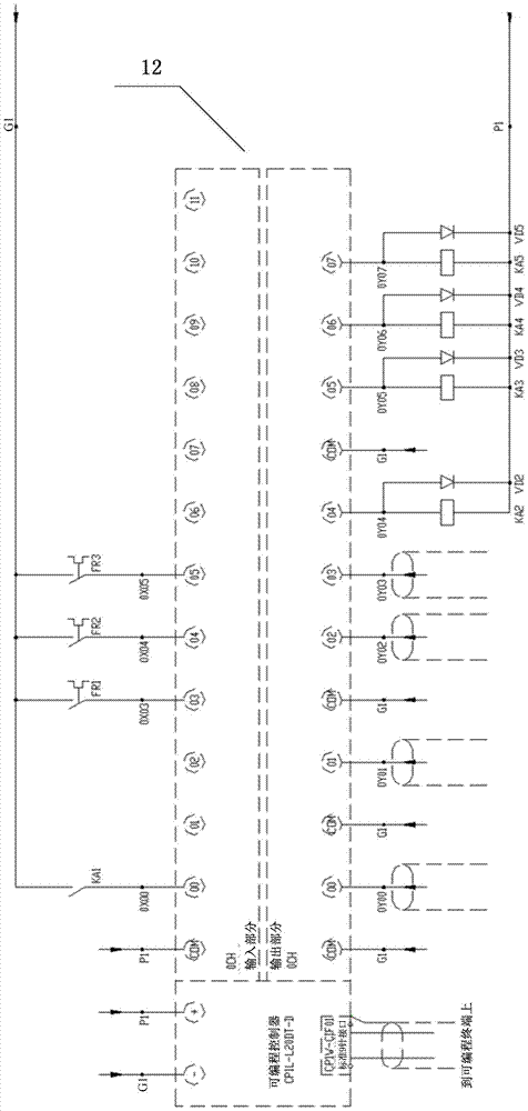
[0054] This embodiment provides a control circuit for an inner circle slicer, such as figure 1 shown, including:

[0055] The total control module 1 inputs corresponding control instructions to the first control module 2 , the stepping motor driver module 3 and the second control module 4 according to processing requirements.

[0056] The first control module 2 is connected with the stepper motor driver module 3, and is used to control the on-off of the stepper motor driver module 3; the stepper motor driver module 3 is used to drive the stepper motor to rotate, Then drive the workbench on the inner circle slicer to produce corresponding displacement.

[0057] The cutter head assembly 5 includes two or more cutter heads, and a motor connected to each cutter head and controlling the rotation of the cutter head. Each cutter head corresponds to a material rod loaded on the workbench.

[0058] The second control module 4 is connected with the motor in the cutter head assembly 5,...

Embodiment 2

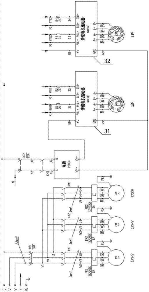
[0071] On the basis of embodiment 1, the inner circle slicer control circuit described in the present embodiment, such as figure 2 As shown, the power module 6 includes a transformer and a switching power supply.

[0072] The primary winding end of the transformer obtains an AC voltage from the power grid to supply power to the first control module 2 , the stepper motor driver module 3 , the second control module 4 and the cutter head assembly 5 .

[0073] The switching power supply is connected to the secondary winding terminal of the transformer, and converts the step-down AC voltage obtained from the secondary winding terminal into a 24V DC voltage; and the output terminal of the switching power supply is connected to the main The voltage receiving end of the control module 1 is connected to provide 24V DC voltage thereto.

[0074] In the inner circle slicer control circuit described in this embodiment, the power module 6 includes a transformer and a switching power suppl...


PUM


Abstract

The invention provides a control circuit of an inside diameter slicing machine. The control circuit comprises a main control module. According to machining requirements, corresponding control instructions are input into a first control module, a stepping motor driver module and a second control module respectively. The first control module is connected with the stepping motor driver module to control the stepping motor driver module to be on or off. The stepping motor driver module drives a stepping motor to rotate to drive a working table on the inside diameter slicing machine to move correspondingly. A tool bit assembly comprises two or more tool bits and motors connected with the tool bits to control the tool bits to rotate. Each tool bit corresponds to a material bar installed on the working table, the second control module is connected with the motors inside the tool bit assembly to control the motors to be turned on or turned off, and then the corresponding tool bits are controlled to rotate or not. A power module supplies power to all the modules. In this way, the inside diameter slicing machine can cut two or more material bars at a time, then the machining efficiency of the inside diameter slicing machine is greatly improved, and the production cost is lowered.

Description

technical field [0001] The invention relates to a control circuit. Specifically, it relates to a control circuit of an inner circle slicer. Background technique [0002] Internal circle slicer is a special equipment for cutting hard and brittle metal and non-metallic materials. Its main working principle is that the internal circle slicer uses the high-speed rotating stainless steel thin tension cutter head to cut the material rod. At the same time, the cooling lubricating fluid is sprayed at the cutting place to perform forced cooling, lubrication and oil discharge on the cutter head. Usually the cutter head There is also a diamond coating on it to increase the cutting force. When the traditional internal circle slicer is working, the operator first uses professional glue to bond the material rod and the bottom plate, and then transfers the glued material rod to the workbench, and then adjusts the horizontal angle, vertical angle, pitch angle, etc. of the material rod. T...

Claims


Application Information

Patent Timeline
Patent Type & Authority Patents(China)
IPC IPC(8): G05B19/414
CPCG05B19/4142
Inventor 赵恋
Owner 赤城县麦特科技有限公司
Features
  • R&D
  • Intellectual Property
  • Life Sciences
  • Materials
  • Tech Scout
  • Unparalleled Data Quality
  • Higher Quality Content
  • 60% Fewer Hallucinations
Learn More