Split type faucet

A split-type, faucet technology, applied in the field of faucets, can solve the problems of reduced production efficiency, complex structure, easy occurrence of air holes, etc., and achieve the effects of improving assembly efficiency, simple assembly process, and reducing assembly strength.

Inactive Publication Date: 2015-01-21
阳雷鸣
View PDF11 Cites 0 Cited by
  • Summary
  • Abstract
  • Description
  • Claims
  • Application Information

AI Technical Summary

Problems solved by technology

The above technical solution does not require a gravity casting process to connect the water nozzle, but since the water outlet connector is inserted into the valve core seat, the valve core seat needs to open an inner channel for the water outlet connector to insert, which increases the complexity of the mold and reduces the production efficiency; In addition, the water outlet joints are all nested in the valve core seat and the water outlet nozzle. The water flows from the water inlet channel into the water outlet joint, and then from the water outlet joint into the water outlet channel. It needs to pass through two joints, which is easy to cause water leakage, and the structure is more complicated. The requirements for the installation process are also very high; in addition, when the outlet pipe is set up or down, the outlet joint is inconvenient to install and unstable, and leakage is more likely to occur
There are also cases where the independently formed water outlet joint is fixed on the valve body by welding or other processes, but the surface temperature is very high during the welding process, and pores are prone to appear, as well as unevenness, which affects the appearance of the product.

Method used


Image

  • Split type faucet

Examples


Embodiment Construction

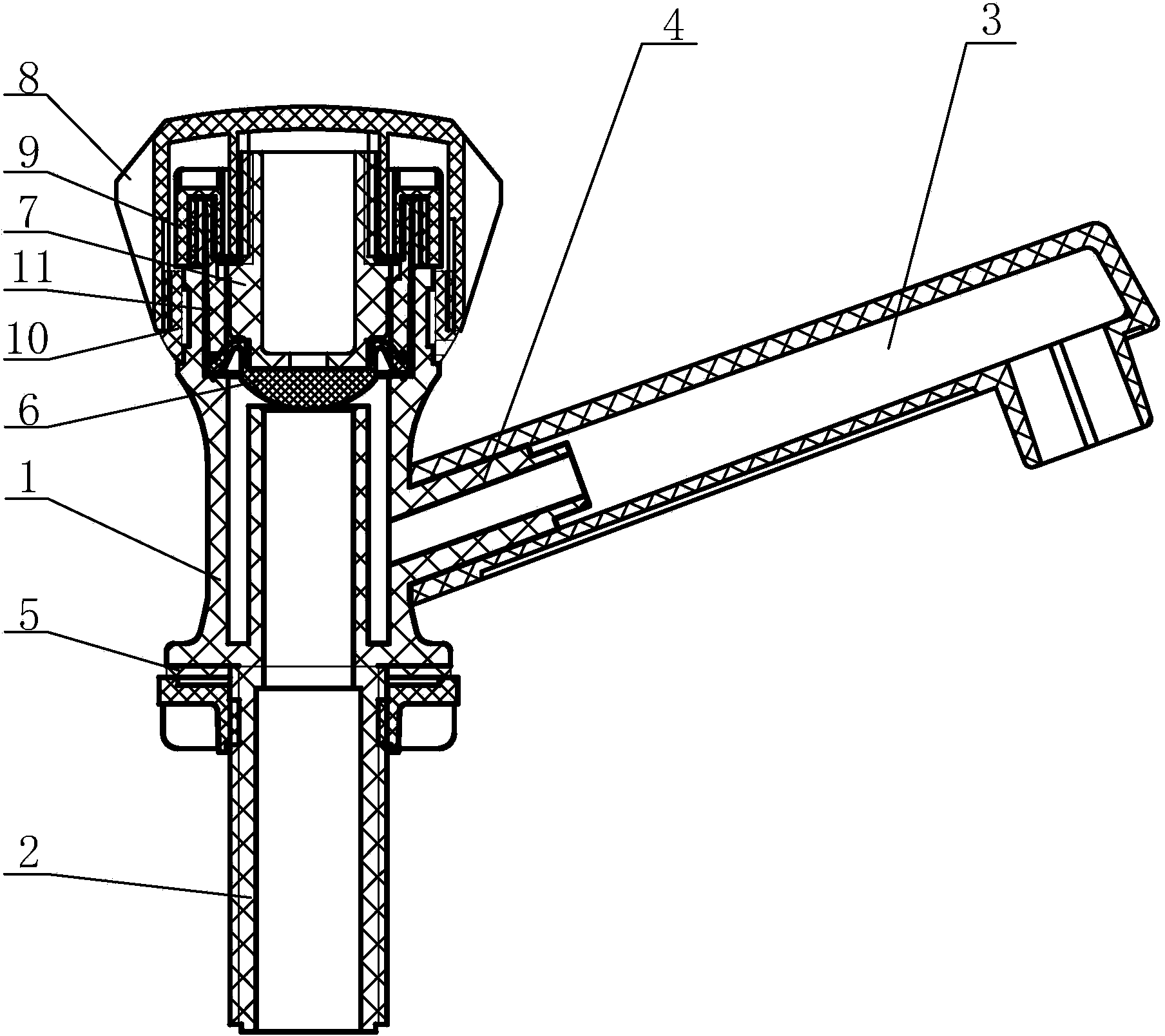
[0014] Such as figure 1 As shown, it is a structural schematic diagram of a split type faucet of the present invention, including a valve body 1, a water inlet pipe 2 connected to the water inlet of the valve body 1, a water outlet pipe 3 connected to the water outlet of the valve body 1, and a The sealing film 6 in the valve body 1, the valve stem 7, and the handle 8 arranged at the upper end of the valve stem 7.

[0015] The water inlet of the valve body 1 is coaxially arranged with the valve stem 7, the outer ring of the water inlet wall is the water inlet chamber, the water outlet is connected with the water inlet chamber, and a circle is arranged on the coaxial line above the water inlet and the water inlet chamber. Cylinder cavity, the guide sleeve 11 is fitted in the cylinder cavity with the valve stem 7 fitted, the sealing film 6 is fixed on the front end surface of the valve stem 7, the film surface of the sealing film 6 seals the port of the water inlet cavity, and t...


PUM


Abstract

The invention discloses a split type faucet which comprises a valve body, a water inlet pipe and a water outlet pipe. The water inlet pipe is communicated with a water inlet of the valve body, the water outlet pipe is communicated with a water outlet of the valve body, the water outlet of the valve body is provided with a water outlet connecting pipe, the water outlet connecting pipe and the water outlet are coaxially arranged, and the water outlet connecting pipe and the valve body are integrally formed. The water outlet connecting pipe is sleeved with one end of the water outlet pipe and the water inlet pipe and the water inlet are coaxially arranged. According to the split type faucet, the water outlet connecting pipe is far shorter than the water outlet pipe, so that a forming die is simplified; the water outlet connecting pipe and the valve body are integrally formed, so that the problem of leakage of the water outlet end is solved, the water outlet connecting pipe is simple in structure, the forming die is further simplified, die removal is easy, manual die removal is changed into mechanical vibration die removal, and production efficiency is high.

Description

technical field [0001] The invention relates to a faucet, in particular to a split type faucet. Background technique [0002] Existing water faucets include a valve body, a water inlet pipe and an outlet pipe communicated with the valve body, and water flows out from the water outlet pipe after entering the valve body through the valve core in the valve body from the water inlet pipe. Among them, there are two ways to connect the outlet pipe and the valve body. One is integrated molding by casting; For example, the Chinese utility model patent whose notification number is CN203453574U discloses a connection structure of a washbasin faucet, including a valve sleeve, a valve core seat arranged in the valve sleeve, and a spout arranged outside the valve sleeve. The channel is provided with a water outlet joint sealed and installed, and the water outlet joint communicates with the water channel. One end of the water outlet joint passes through the valve sleeve and is sealed and...

Claims


Application Information

Patent Timeline
Patent Type & Authority Applications(China)
IPC IPC(8): F16K1/32F16K27/02F16K31/60
CPCF16K1/32F16K27/0209
Inventor 阳雷鸣
Owner 阳雷鸣
Why Eureka
Try Eureka