
Method for optimum design of planar variable-pitch grating

A technology of variable pitch grating and optimized design, applied in the field of spectroscopy, which can solve problems such as large errors

Inactive Publication Date: 2015-01-21
CHANGCHUN INST OF OPTICS FINE MECHANICS & PHYSICS CHINESE ACAD OF SCI
View PDF3 Cites 5 Cited by
  • Summary
  • Abstract
  • Description
  • Claims
  • Application Information

AI Technical Summary

Problems solved by technology

[0004] In order to solve the problem that there is a large error between the reticle density function and the expected reticle density function of the variable grating grating produced by the existing method, the present invention provides an optimal design method for a plane variable grating grating

Method used


Image

  • Method for optimum design of planar variable-pitch grating
  • Method for optimum design of planar variable-pitch grating
  • Method for optimum design of planar variable-pitch grating

Examples


specific Embodiment approach 1

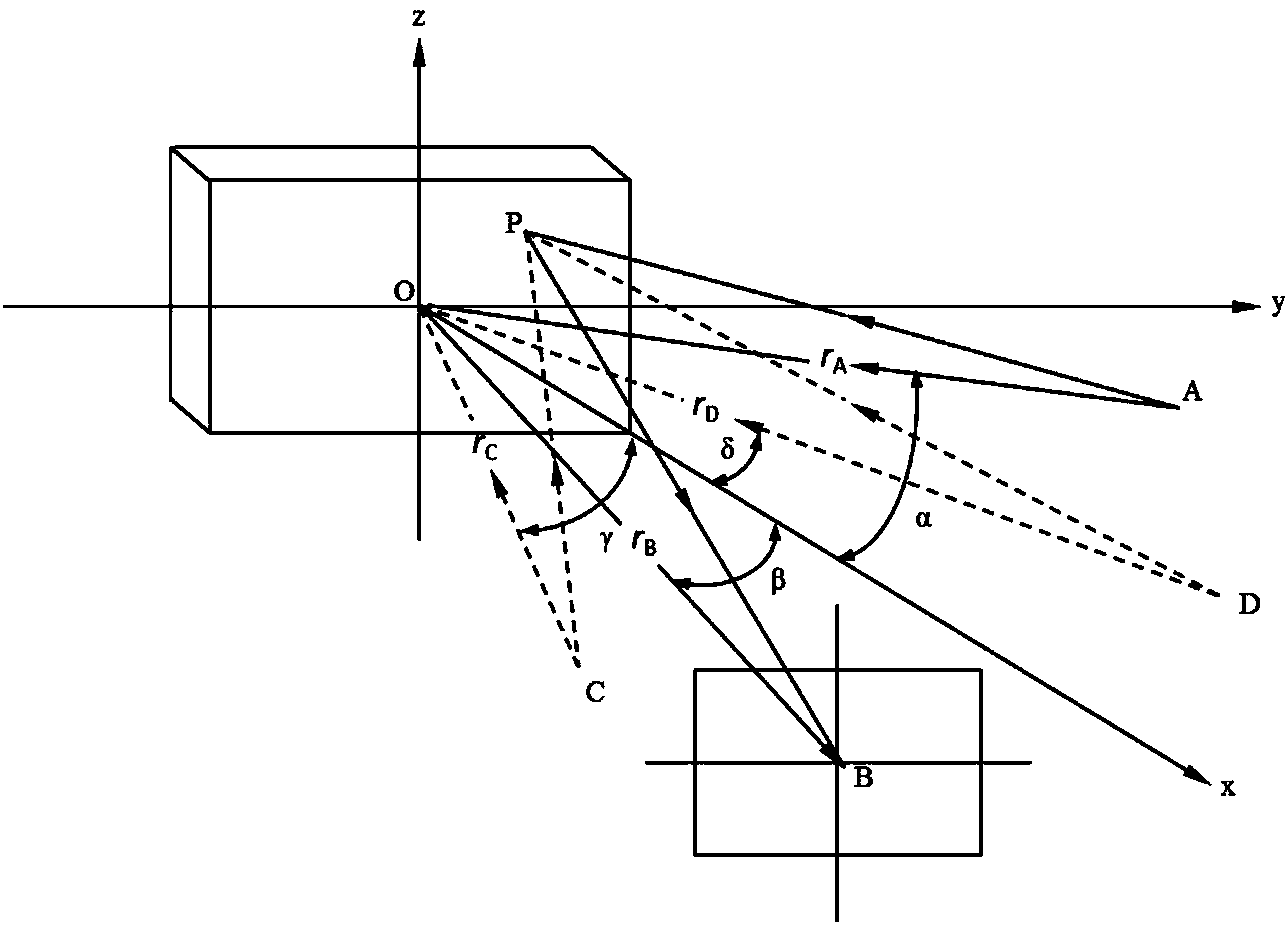
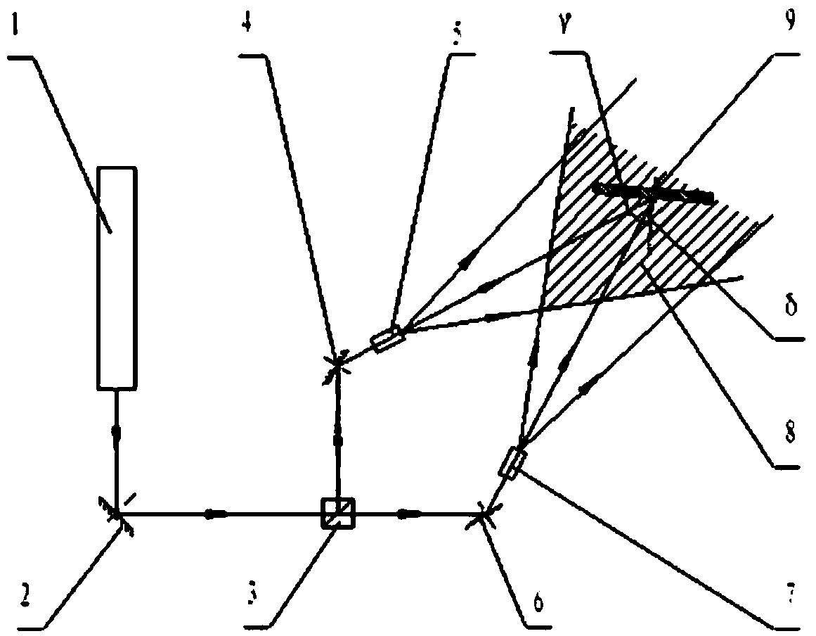
[0031] Specific implementation mode 1. Combination figure 1 with figure 2 In this embodiment, the optimal design method of the variable pitch grating must go through strict theoretical design before making the variable pitch grating. Without a reasonable theoretical design, it is unimaginable to make the variable pitch grating. The theoretical design process is described in detail below.

[0032] Starting from the optical path function, calculate the optical path difference at any point on the substrate according to the theory of spherical wave geometry, apply Fermat's principle to the optical path function, and expand it in series, finally get the desired reticle of the variable pitch grating density function, figure 1 Schematic diagram of spherical wave exposure system for variable pitch grating. Mainly consider the conformity of the reticle density in the meridian plane of the grating, ignore the curvature of the reticle for the time being, let z=0, simplify the expecte...


PUM


Abstract

The invention discloses a method for optimum design of a planar variable-pitch grating and relates to the spectrum technical field. By the adoption of the method, the problem that the groove density function of a variable-pitch grating manufactured with existing methods is quite different from an expected groove density function is solved. According to the method, the meridian expected groove density function of the planar variable-pitch grating is obtained by means of a spherical wave exposure system, the deviate focus, meridian coma and spherical aberration of the planar grating are obtained according to the eikonal function of the variable-pitch grating, the variable-pitch grating is made to focus according to a grating equation, the expected groove density function, the value of the deviate focus F20, the value of the meridian coma F30 and the value of the spherical aberration F40, the meridian coma and the spherical aberration are zero, the expected groove density function coefficient optimized spherical wave logging parameters of the planar variable-pitch grating are obtained, the integral function of the square of the difference between expected groove density and designed groove density of each point on the surface of a substrate of the grating serves as an objective function and is optimized, the minimum value is obtained, and then optimum design of the planar variable-pitch grating is achieved. By the adoption of the method, computing time is shortened, and computing efficiency is improved.

Description

technical field [0001] The invention relates to the field of spectrum technology, in particular to an optimal design method of a variable pitch grating. Background technique [0002] The variable pitch grating mainly has the following main features: self-focusing, aberration correction ability and flat focal field, which can reduce the optical components in the optical system, reduce stray light, and improve diffraction efficiency and resolution. The above-mentioned advantages of the planar variable pitch grating can only be realized by strictly designing the grating line density function according to the requirements of the spectroscopic instrument. [0003] There are two methods of making variable pitch gratings, mechanical scribing and holographic exposure. Compared with ruled gratings, holographic gratings are easy to manufacture, easy to change the shape of the ruled lines, more types of substrates can be produced, and have the advantages of no ghost lines and low stra...

Claims


Application Information

Patent Timeline
IPC IPC(8): G02B5/18
CPCG02B27/0012G02B5/1847
Inventor 巴音贺希格姜岩秀李文昊杨硕赵旭龙吴娜
Owner CHANGCHUN INST OF OPTICS FINE MECHANICS & PHYSICS CHINESE ACAD OF SCI
Learn More