A liquid crystal based infrared beam polarization control chip

A technology of polarization control and liquid crystal, which is applied in the direction of instruments, optics, static indicators, etc., can solve the problems of narrow spectrum range, difficult flexible access, fixed polarization state, etc. The effect of variable control

Active Publication Date: 2017-04-26
HUAZHONG UNIV OF SCI & TECH
View PDF4 Cites 0 Cited by
  • Summary
  • Abstract
  • Description
  • Claims
  • Application Information

AI Technical Summary

Problems solved by technology

[0003] The main defects of the technical measures currently used to construct and adjust the infrared polarization state are: (1) The infrared polarizers based on discrete arrangements can only establish a specific infrared electromagnetic vibration orientation and fine-tune them; The specific polarization state of the beam has a relatively narrow spectral range, and the polarization state is relatively fixed, and the polarization can only be fine-tuned through the relative movement between the film-coated substrates; (3) Only the polarization state of a specific orientation can be established and fine-tuned through multi-beam interference (4) Based on the diffraction effect, a specific polarized light field can only be integrally constructed in a large space, and the effect of adjusting the beam polarization state by adjusting the phase of the diffraction structure is very limited; (5) Due to the volume, quality and working mode, etc. It is difficult to flexibly connect to the optical path or couple with other infrared structures; (6) It is difficult for conventional polarization technology to carry out adjustable chip transformation based on modern micro-nano optical and optoelectronic technology

Method used


Image

  • A liquid crystal based infrared beam polarization control chip
  • A liquid crystal based infrared beam polarization control chip
  • A liquid crystal based infrared beam polarization control chip

Examples


Embodiment Construction

[0025] In order to make the object, technical solution and advantages of the present invention clearer, the present invention will be further described in detail below in conjunction with the accompanying drawings and embodiments. It should be understood that the specific embodiments described here are only used to explain the present invention, not to limit the present invention. In addition, the technical features involved in the various embodiments of the present invention described below can be combined with each other as long as they do not constitute a conflict with each other.

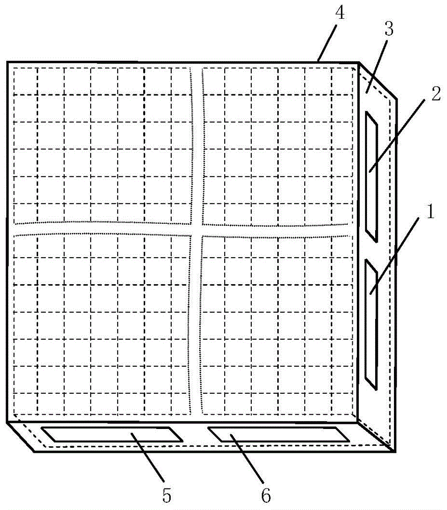
[0026] like figure 1 As shown, the liquid crystal-based infrared beam polarization control chip of the present invention includes: a chip housing 4, and an arrayed liquid crystal polarization control structure 3 composed of patterned electrodes and patterned liquid crystal initial anchor wire clusters.

[0027] The arrayed liquid crystal polarization control structure 3 is located in the chip h...


PUM


Abstract

The invention discloses a liquid-crystal-based infrared wave beam polarization control chip. The liquid-crystal-based infrared wave beam polarization control chip comprises a chip shell (4) and an array liquid crystal polarization control structure (3) located in the chip shell (4). The chip shell (4) is provided with a first drive control signal input port (1), a second drive control signal input port (2), a third drive control signal input port (5) and a fourth drive control signal input port (6). Infrared light waves are dispersed into a sub-wave-beam array according to the array scale and the arrangement situation of the liquid crystal polarization control structure after entering the array liquid crystal polarization control structure of the chip. The specific polarization-state transmission beam wave is obtained by making sub-wave-beams interact with liquid crystal molecules excited by a controlled electric field, conducting phase delay operation in the horizontal direction, the vertical direction, the 45-degree direction, the 135-degree direction and the like and then conducting beam combining. The liquid-crystal-based infrared wave beam polarization control chip is compact in structure, and electronic control establishment or solidification or modulation in the infrared wave beam polarization state can be conducted.

Description

technical field [0001] The invention belongs to the technical field of infrared beam precision measurement and control, and more specifically relates to a liquid crystal-based infrared beam polarization control chip. Background technique [0002] In general, infrared radiation emitted from artificial light sources such as coherent lasers or various thermal and thermal light emitters has a specific polarization state. The relatively uniformly polarized infrared light emitted by the sun, the earth, and other stars, after being scattered, reflected, transmitted by the atmosphere, or interacted with other material structures, presents a fixed polarization form that is affected and constrained by the physical properties of the propagation medium, such as typical linear polarization, Circular polarization and elliptical polarization etc. The material structure of a specific form and energy state, based on the intrinsic resonance response of the inherent electromagnetic structure ...

Claims


Application Information

Patent Timeline
Patent Type & Authority Patents(China)
IPC IPC(8): G02F1/1343G02F1/133G01J3/12
CPCG02F1/0136G02F1/133528G02F1/134309G02F1/134318
Inventor 张新宇罗俊佟庆雷宇桑红石张天序谢长生
Owner HUAZHONG UNIV OF SCI & TECH
Why Eureka
Try Eureka