A spiral rising processing equipment with four chutes

A processing equipment and spiral rising technology, which is applied to metal processing equipment, components with teeth, mechanical equipment, etc., can solve problems such as low efficiency of worm transmission, difficulty in ensuring the shape and position accuracy of tooth grooves, and troublesome worm gear tooth shape, etc.

Inactive Publication Date: 2016-06-29
国网山东省电力公司沂源县供电公司
View PDF3 Cites 0 Cited by
  • Summary
  • Abstract
  • Description
  • Claims
  • Application Information

AI Technical Summary

Problems solved by technology

4. The efficiency of worm transmission is low, and it is generally believed that the efficiency of worm transmission is lower than that of gear transmission
However, the shape processing and manufacturing of the worm gear tooth profile is troublesome, and it is difficult to ensure the accuracy of the processed tooth groove shape and position
[0003] In particular, in some specific application areas, such as soft materials (such as plastics) processing, traditional metal processing methods will be difficult to meet the requirements of reducing costs and improving processing speed and accuracy

Method used


Image

  • A spiral rising processing equipment with four chutes
  • A spiral rising processing equipment with four chutes
  • A spiral rising processing equipment with four chutes

Examples


Embodiment Construction

[0014] Attached below Figure 1-2 , The present invention will be described in detail.

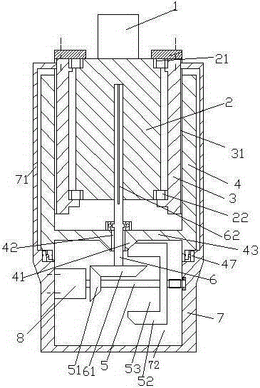
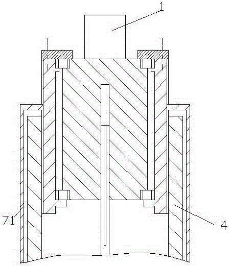
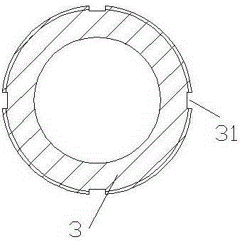
[0015] A spiral ascending processing equipment with four sliding grooves for processing a blank 1 into a worm. The processing equipment includes a blank carrier 2, a sleeve with an external thread 3, and a drive sleeve with an internal thread 4 and the frame 7. The blank carrier 2 is used to carry the blank 1. The upper end and the lower end of the blank carrier 2 are opposite to the outer threaded sleeve 3 through the upper bearing 21 and the lower bearing 22 respectively. The externally threaded sleeve 3 is fixedly installed in the externally threaded sleeve 3, and the externally threaded sleeve 3 is threadedly fitted into the internally threaded drive sleeve 4, and the internally threaded drive sleeve 4 The lower end of the frame 7 is rotatably mounted on the frame 7 through a thrust bearing 47. The frame 7 has a cavity 72 inside. In the cavity 72, a drive motor is fixed on the left inner...


PUM


Abstract

The invention discloses spiral rising type processing equipment with four sliding grooves. The spiral rising type processing equipment is used for processing a blank piece (1) into a worm and comprises a blank-piece bearing piece (2), a sleeve (3) with external threads, a driving sleeve (4) with internal threads and a rack (7), wherein the blank-piece bearing piece (2) is used for bearing the blank piece (1); relative to the sleeve (3) with the external threads, the upper end and the lower end of the blank-piece bearing piece (2) are respectively and fixedly arranged in the sleeve (3) with the external threads by an upper bearing (21) and a lower bearing (22) in an axial manner; the sleeve (3) with the external threads is matched in the driving sleeve (4) with the internal threads by threads; the lower end of the driving sleeve (4) with the internal threads can be rotatably arranged on the rack (7) by a thrust bearing (47); the rack is internally provided with a cavity (72).

Description

Technical field [0001] The application relates to the field of worm machining, specifically a spiral-rising machining equipment with four sliding grooves. Background technique [0002] The worm drive is composed of a worm and a worm wheel. Generally, the worm is the driving part. Worm and screw have right-handed and left-handed points. Worm drive has the following advantages: 1. Large transmission ratio and compact structure. The number of worm heads is represented by Z1 (generally Z1=1~4), and the number of worm gear teeth is represented by Z2. It can be seen from the transmission ratio formula I=Z2 / Z1 that when Z1=1, that is, the worm is single-headed, the worm must turn Z2 to turn the worm wheel to make one revolution, so a large transmission ratio can be obtained. Generally, in power transmission, take Transmission ratio I=10-80; in the indexing mechanism, I can reach 1000. Such a large transmission, such as gear transmission, requires a multi-stage transmission. Therefor...

Claims


Application Information

Patent Timeline
Patent Type & Authority Patents(China)
IPC IPC(8): B23F13/02B23Q5/28F16H37/02
Inventor 王晓晨陈德平王建民亓君红张仁东张仕花张峰
Owner 国网山东省电力公司沂源县供电公司
Why Eureka
Try Eureka