
Arc type self-adaptive stud welding gun

An adaptive, stud welding technology, applied in arc welding equipment, welding equipment, manufacturing tools, etc., can solve the problem that the moving iron core is stuck in the fixed sleeve, increase the main shaft body and linear bearing, and the moving iron core and the fixed sleeve. The problems of wear amount and low welding efficiency can achieve the effect of basically the same height of the welding feet, flexible and reliable axial sliding, and high welding qualification rate.

Active Publication Date: 2015-01-28
SUZHOU MENGZHIJIE WELDING TECH
View PDF8 Cites 3 Cited by
  • Summary
  • Abstract
  • Description
  • Claims
  • Application Information

AI Technical Summary

Problems solved by technology

[0003] The main disadvantages of the stud welding gun with the above structure are: (1) During the actual use of the stud welding gun, due to the existence of factors such as machining errors, installation errors, and thermal deformation of the welding gun shell, the linear bearing and the fixed sleeve will The concentricity is not high, which will increase the resistance when the main shaft body and the moving iron core, which are fixedly connected at the head and tail, increase the resistance when moving axially, and greatly increase the wear between the main shaft body and the linear bearing, as well as the moving iron core and the fixed sleeve, seriously Otherwise, the moving iron core will be stuck in the fixed sleeve or the moving iron core cannot be inserted into the fixed sleeve, so that the axial movement of the main shaft body cannot be realized, and the welding work cannot be carried out normally; (2) Before starting the welding work, the After setting the aluminum sleeve on the head of the welding torch, insert the stud into the integrated chuck seat, and then turn the torch head down so that the front end of the aluminum sleeve is pressed against the welding plate, and the front end of the stud is also pressed against the welding plate On the parts, since the main shaft body and the moving iron core are fixedly connected, and the studs will inevitably have machining errors during the machining process, when the actual length of the studs is slightly longer, the long studs will pass through the main shaft body Compress the return spring and make the main shaft body and the moving iron core slide towards the tail end together, so that the lifting gap between the moving iron core and the static iron core becomes smaller, so that the arc striking distance during welding arc striking is shortened, and it is easy to fail to strike the arc phenomenon, which greatly reduces the qualified rate of welding, and the welding efficiency is relatively low; (3) When the arc is struck under the guidance of the main shaft, a molten pool will be formed between the welded plate and the stud. Under the action, the spindle body quickly returns to its original position, thereby quickly pressing the stud into the molten pool to form a welded joint. Due to the instantaneous impact force of the compressed return spring, the instantaneous impact force will cause the stud to press into the molten pool. Splash the molten metal in the molten pool, thus affecting the welding quality

Method used


Image

  • Arc type self-adaptive stud welding gun
  • Arc type self-adaptive stud welding gun
  • Arc type self-adaptive stud welding gun

Examples


Embodiment Construction

[0026] The technical solutions of the present invention will be further described in detail below in conjunction with the accompanying drawings and preferred embodiments.

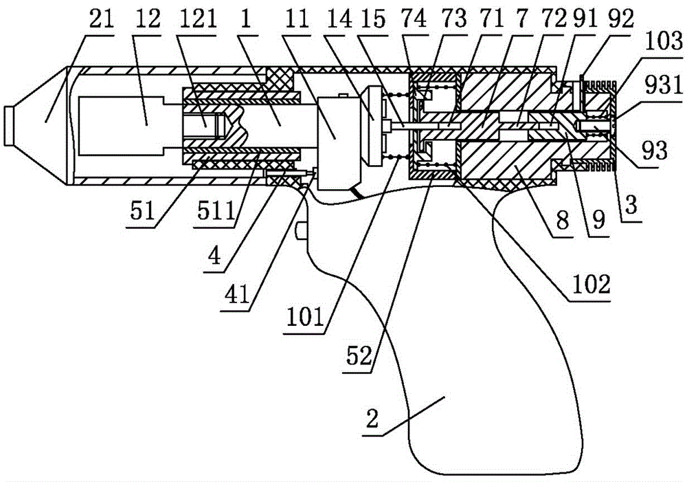
[0027] Such as figure 1As shown, the drawn-arc self-adaptive stud welding torch of the present invention includes: a welding torch housing 2 with a cavity, in which a main shaft body 1 and a moving iron are arranged in sequence from front to end in the cavity Core 7, a fixed sleeve 8 and a static iron core 9 with a coil inside, and a control circuit device that provides operating current to the main shaft body 1 and the coil is also provided in the welding torch housing 2; it is fixed in the cavity of the welding torch housing 2 A shaft sleeve 51 is provided, and the main shaft body 1 is penetrated in the shaft sleeve 51 and can slide axially in the shaft sleeve 51. The grinding bush 511, the wear-resistant bush 511 and the main shaft body 1 are electrically insulated from each other, the main shaft body 1...


PUM


Abstract

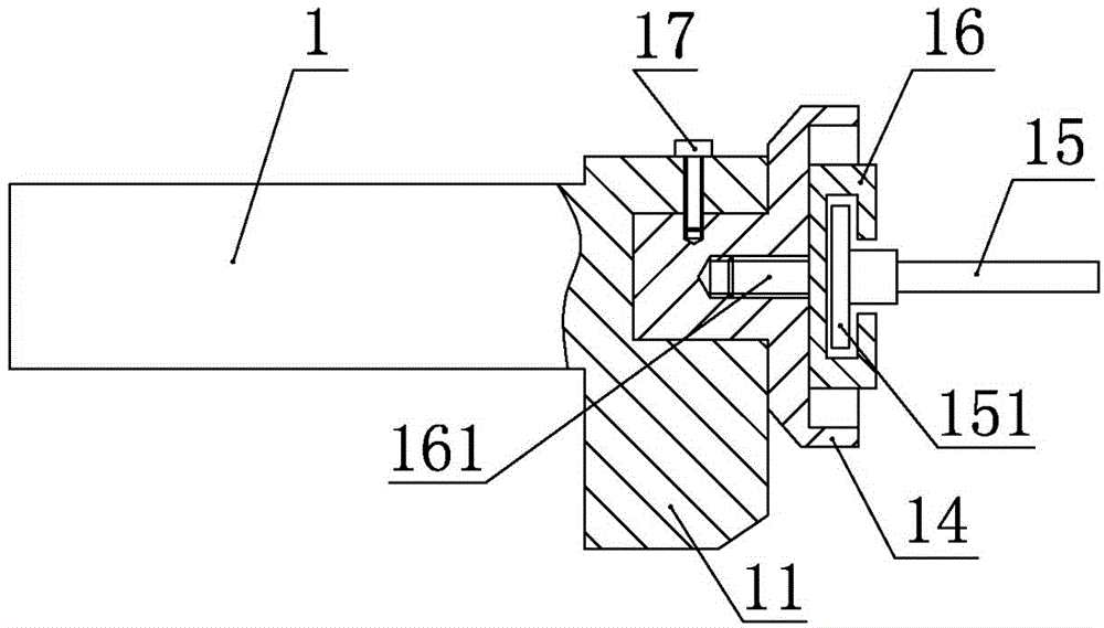
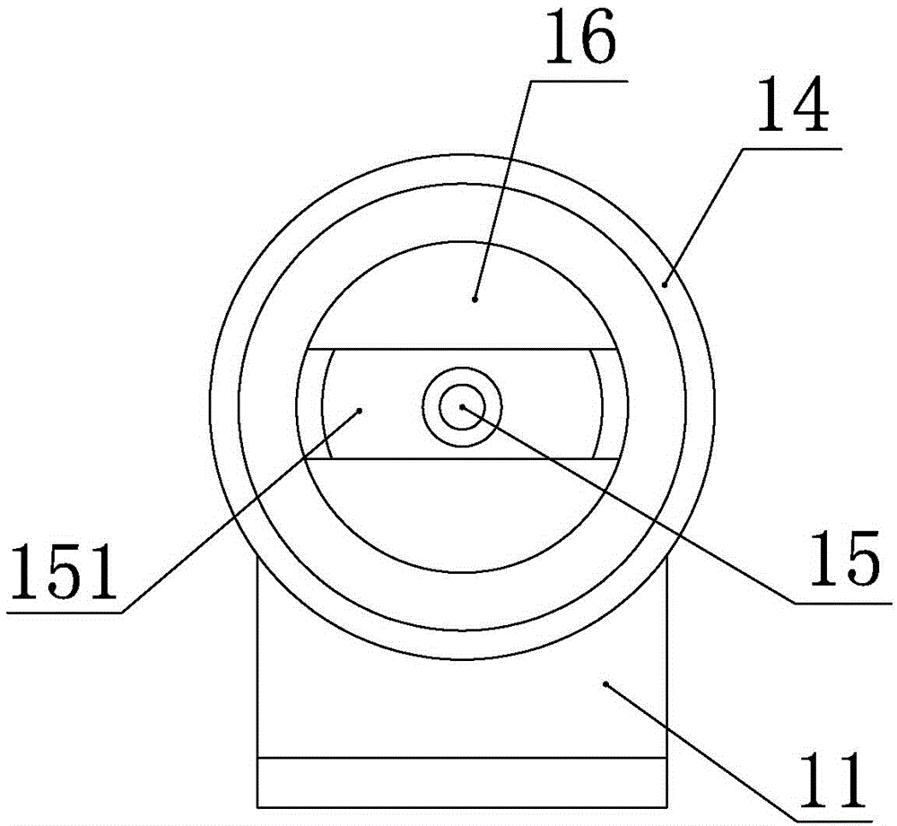
The invention discloses an arc type self-adaptive stud welding gun. The interior of a cavity of a welding gun casing is provided with a main shaft body, a movable iron core, a fixing sleeve, a stationary iron core and a control circuit device, the front end of the main shaft body is provided with an integral clamping head seat, the interior of the fixing sleeve is provided with a coil, the main shaft body is movably arranged in a shaft sleeve in a penetrating way, the shaft sleeve is fixedly arranged in the cavity, the front end of the fixing sleeve is movably inserted into the movable iron core, the tail end of the fixing sleeve is inserted into the stationary iron core, a lifting clearance is formed between the movable iron core and the stationary iron core, a reset structure is arranged in the welding gun casing and is used for resetting the main shaft body after arc striking, a damper is fixedly arranged in the welding gun casing and is used for the main shaft body to stably reset, a self-adaptive structure is arranged between the main shaft body and a driving shaft and is used for the driving shaft to adjust the self position, the driving shaft is arranged at the tail end of the main shaft body in an electric insulation way, and a locking structure with an engagement and disengagement function is arranged between the driving shaft and the movable iron core. The arc type self-adaptive stud welding gun has the advantages that the main shaft body can be stably reset after arc striking, the smooth sliding of the main shaft body along the axial direction is guaranteed, and the set lifting clearance is not changed.

Description

technical field [0001] The invention relates to a stud welding torch, in particular to a drawn arc self-adaptive stud welding torch. Background technique [0002] At present, the common drawn arc stud welding torch has the following structure: a welding torch housing with a cavity, in which a main shaft body, a moving iron core, and a fixed coil with a coil are arranged in sequence from front to end in the cavity of the welding torch housing. The sleeve and the static iron core are also provided with a control circuit device for supplying working current to the main shaft body and the coil in the welding torch housing. It is installed in the linear bearing and can slide axially in the linear bearing; the main shaft body is sleeved with a return spring that can reset the main shaft body after the arc is struck. Between the flange and the fixed sleeve, the front end of the main shaft body is connected with the integrated chuck seat used to install the stud. The tail end of th...

Claims


Application Information

Patent Timeline
IPC IPC(8): B23K9/06B23K9/20
CPCB23K9/067B23K9/202
Inventor 顾红刚顾鑫
Owner SUZHOU MENGZHIJIE WELDING TECH
Learn More