The head structure of the wall grinder

A grinding machine and machine head technology, which is applied to the parts of grinding machine tools, machine tools suitable for grinding workpiece planes, grinding machines, etc., can solve the problem that the wall cannot be easily observed, the grinding effect is not satisfactory, and it is difficult to maintain Balance and other issues to achieve the effect of light weight, easy maintenance and long service life

Active Publication Date: 2017-10-20
傅月华 +1
View PDF6 Cites 0 Cited by
  • Summary
  • Abstract
  • Description
  • Claims
  • Application Information

AI Technical Summary

Problems solved by technology

However, even if the lighting is used for auxiliary observation, the eyes still cannot easily observe the unevenness of the wall, resulting in unsatisfactory polishing effect, and the power of the lighting is 1000w, which is commonly known as the little sun, and the energy consumption is relatively high
[0004] Moreover, the wall grinder can only be used to grind the wall, but not the roof. The reason is that when the roof is polished, the grinding disc is horizontal unless the operator can keep the operating handle perpendicular to the grinding disc, so it is difficult to maintain balance.

Method used


Image

  • The head structure of the wall grinder
  • The head structure of the wall grinder
  • The head structure of the wall grinder

Examples


Embodiment 1

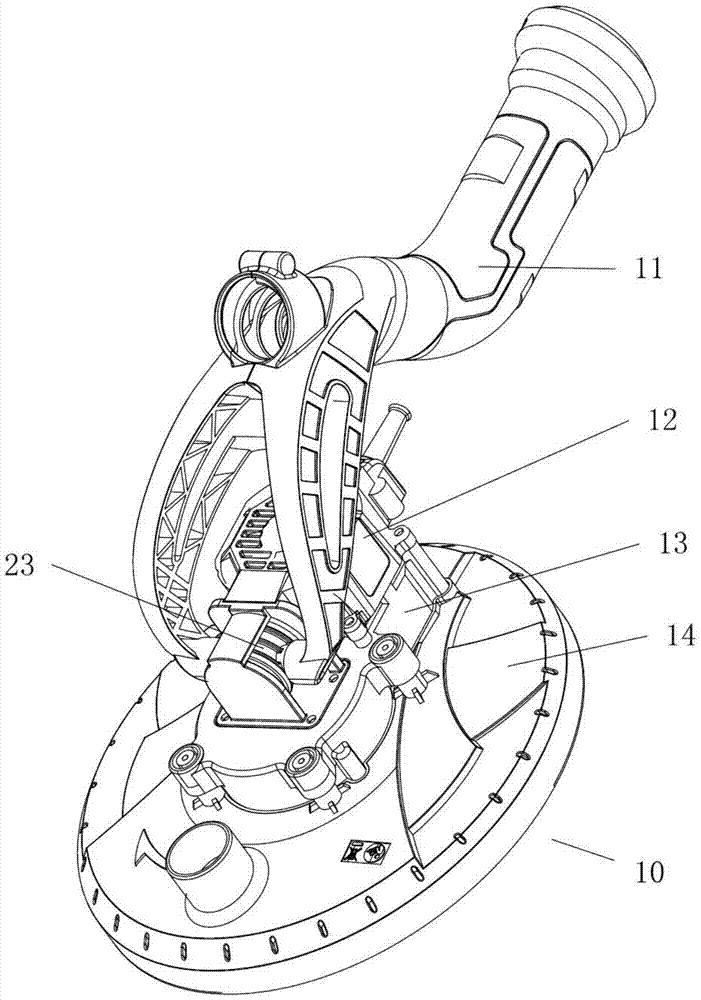
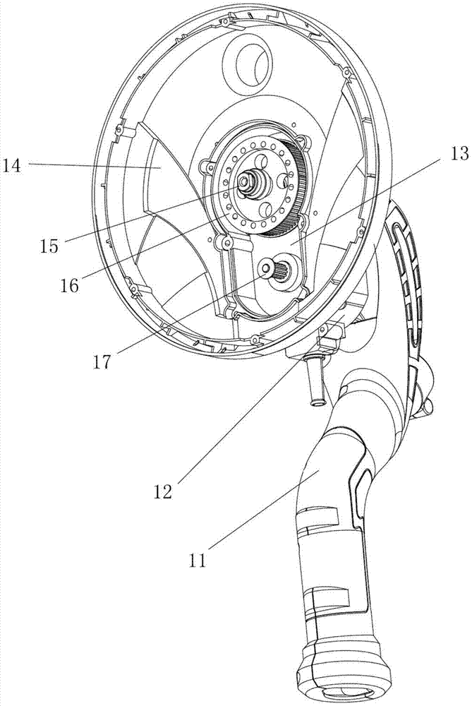
[0047] Example 1, such as Figure 1-2As shown, the head structure of the wall grinder includes a cover 14, a transmission chamber 13 arranged on the cover 14, and a drive motor, the drive motor is a brushless DC motor 12, and the brushless DC motor 12 is installed on the transmission On the chamber 13, a deceleration transmission mechanism is provided in the transmission chamber 13, and the motor shaft of the brushless DC motor 14 stretches into the transmission chamber and drives the deceleration transmission mechanism, and the output shaft 15 of the transmission mechanism drives the grinding disc assembly (not shown). figure 2 In the figure, the bottom cover of the transmission chamber is drawn, and the peripheral side of the bottom cover is connected with the upper cover of the transmission chamber by bolts.

[0048] Preferably, the reduction transmission mechanism includes a first synchronous pulley 17 and a second synchronous pulley 16, which are connected by a synchrono...

Embodiment 2

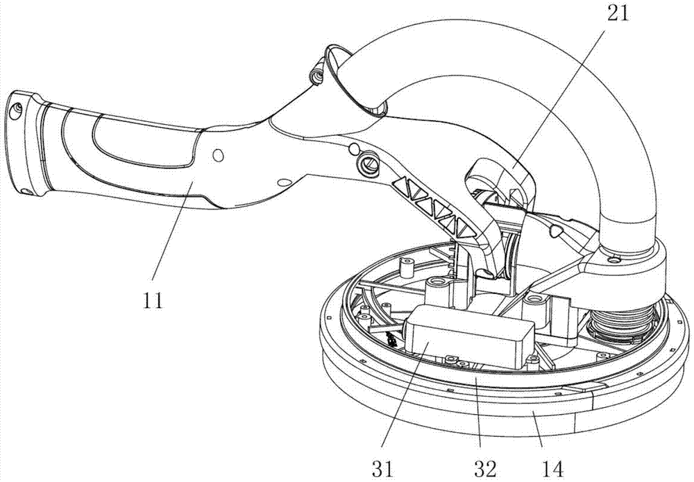
[0050] Example 2, such as Figure 3-6 As shown, this embodiment is improved on the basis of Embodiment 1, wherein a light strip assembly is provided on the protective cover 14 of the machine head, and the light strip assembly includes an LED light strip 33 and a lampshade 32; the protective cover The LED light strip 33 is installed on the peripheral side of 14, the lampshade 32 covers the LED light strip 33 and prevents dust from touching the LED light strip 33, the light emitted by the LED light strip 33 passes through the lampshade 32 and shines on the protective cover 14 side wall. The LED lamp of the present invention is installed on the protective cover. Compared with the design of the existing lighting lamp (installed on the lower side of the middle part of the operating handle), the light emitted by the LED lamp reaches people's eyes after being reflected by the wall. The position of the LED lamp and The position of the eyes is more in line with the optical design, mak...

Embodiment 3

[0059] Example 3, such as Figure 7-11 As shown, this embodiment is improved on the basis of Embodiment 1, wherein the left and right pin shafts of the machine head 10 are connected to the front fork 21 of the front handle 11 (although only the front fork is shown in the figure 21 and the right pin 22, naturally, the cooperation of the front fork 21 and the left pin adopts the same structure), in the left and right pins, at least one of the pins is equipped with a torsion spring, the present embodiment Among them, the torsion spring is only arranged on the right pin shaft 22, the base 25 of the torsion spring is sleeved on the right pin shaft 22, and the end 201 inside the base is connected with the right pin shaft 22. The outer end of the base 25 extends to form a hook 26, which can hook the front fork 21 and turn the machine head 14 at a certain angle (in this embodiment, when the operating handle is lifted vertically, the torsion spring makes the machine The grinding disc ...


PUM


Abstract

The invention belongs to the technical field of wall surface grinding machines, and in particular relates to a machine head structure of a wall surface grinding machine. The machine head structure of the wall surface grinding machine comprises a protection cover, a transmission chamber arranged on the protection cover and a driving motor, wherein the driving motor is a brushless direct-current motor, the brushless direct-current motor is installed on the transmission chamber, a speed reducing transmission mechanism is arranged in the transmission chamber, a motor shaft of the brushless direct-current motor stretches into the transmission chamber and drives the speed reducing transmission mechanism, and an output shaft of the transmission mechanism drives a grinding disc assembly. Since the motor shaft of the brushless direct-current motor drives the grinding disc assembly through the speed reducing transmission mechanism, the structure is simple, the transmission efficiency is high, the noise is low, the service life is long and the maintenance is facilitated; since the speed reducing transmission mechanism is a synchronous belt pulley mechanism, the speed reducing transmission mechanism can adapt to severe working environments of the grinding machine and is dustproof; since the transmission chamber is a magnesium alloy part and the protection cover is an ABS (Acrylonitrile Butadiene Styrene) engineering plastic part, by adopting the design, the overall weight of the machine head is lighter and the use is facilitated.

Description

technical field [0001] The invention belongs to the technical field of wall grinding machines, in particular to a head structure of a wall grinding machine. Background technique [0002] Wall sanders are a well-established technology for sanding and cleaning walls before they are painted, painted or wallpapered. In the prior art, the driving motors of the machine head all use brushed motors, and the transmission mechanism from the driving motor to the output shaft is relatively complicated, and the transmission mechanism has a high demand for dust protection (a large amount of dust will be generated during the grinding process), and the cost is relatively high. Large, average service life, loud noise, not easy to maintain; [0003] In addition, during the grinding process, people need to use their eyes to observe whether the wall has been polished smoothly; in order to enable people's eyes to observe the flatness of the wall easily, the handle of the existing wall grinder i...

Claims


Application Information

Patent Timeline
Patent Type & Authority Patents(China)
IPC IPC(8): B24B7/18B24B41/04
CPCB24B7/18B24B41/04
Inventor 李挺进陈敏叶志浩沈游方童龙华
Owner 傅月华
Why Eureka
Try Eureka