Continuous tempering furnace of roller hearth plates and annealing method thereof

A tempering furnace and roller hearth technology, applied in furnaces, heat treatment furnaces, furnace types, etc., can solve the problems of high investment cost, large equipment footprint, waste of production capacity, etc., and achieve high furnace temperature control accuracy and plate production quality Good, good furnace temperature uniformity

Active Publication Date: 2015-01-28
WISDRI WUHAN WIS IND FURNACE
View PDF7 Cites 8 Cited by
  • Summary
  • Abstract
  • Description
  • Claims
  • Application Information

AI Technical Summary

Problems solved by technology

However, for tempering furnaces, especially medium and low temperature tempering furnaces, the furnace temperature is between 200 and 400°C. Due to the relatively low temperature, the heat transfer method has changed from radiation-based heat transfer to heat convection. , using traditional open flame or radiant tube heating, there are problems of slow heating speed and poor temperature uniformity, so the product quality cannot be guaranteed, which is not conducive to the development of high-end products
[0003] For this reason, in order to realize the medium and low temperature heat treatment process of steel plates, trolley-type heat treatment furnaces are usually used. The principle is to conduct low-temperature heating by feeding hot gas with controllable temperature. The output is low and the steel plate is easily deformed
In addition, the tempering methods of the tempering furnace include high-temperature tempering, medium-temperature tempering, and low-temperature tempering. Generally, it is necessary to build a medium-high temperature tempering furnace and a low-temperature tempering furnace to achieve high-temperature tempering and medium-temperature tempering respectively. And low-temperature tempering, so there are problems such as large equipment footprint, high investment cost and waste of capacity in intermittent production

Method used


Image

  • Continuous tempering furnace of roller hearth plates and annealing method thereof
  • Continuous tempering furnace of roller hearth plates and annealing method thereof
  • Continuous tempering furnace of roller hearth plates and annealing method thereof

Examples


Embodiment Construction

[0024] It should be understood that the specific embodiments described herein are only used to explain the present invention, but not to limit the present invention.

[0025] The invention proposes a roller hearth type continuous tempering furnace for plates.

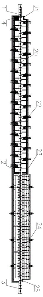
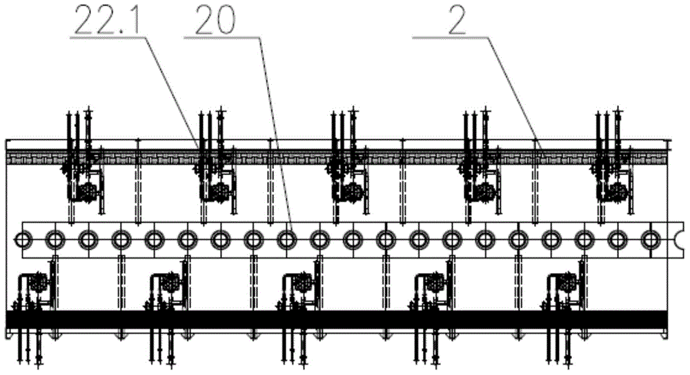
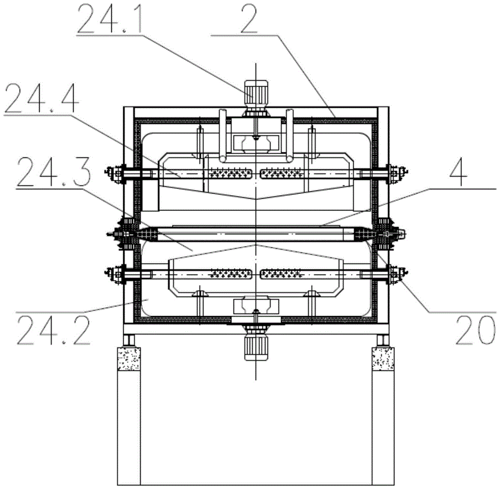
[0026] refer to Figure 1 to Figure 3 , figure 1 It is a schematic structural diagram of a preferred embodiment of the roller hearth type continuous tempering furnace for sheet metal; figure 2 It is a schematic structural diagram of an open fire heating section in a preferred embodiment of the roller hearth type continuous tempering furnace for sheet metal; image 3 It is a schematic cross-sectional structure diagram of the strong convection heat preservation section in the preferred embodiment of the roller hearth type continuous tempering furnace for plates of the present invention.

[0027] In this preferred embodiment, the roller hearth type continuous tempering furnace for sheet metal includes a furnace body 2 ...


PUM


Abstract

The invention discloses a continuous tempering furnace of roller hearth plates. The continuous tempering furnace comprises a furnace body, a feeding device and a discharging device which are installed at the two ends of the furnace body, wherein the furnace body comprises a flame heating segment and strong convection heat preservation segment connected with the flame heating segment, the hearth of the strong convection heat preservation segment is communicated with the hearth of the flame heating segment, the furnace body is provided with a conveying roller way used for conveying plates, the conveying roller way penetrates through the hearths of the strong convection heat preservation segment and the flame heating segment, a flame heating device with adjustable firepower is arranged in the flame heating segment, and a strong convection spray heating device used for circulating heating and spraying hot air is arranged on the strong convection heat preservation segment; the feeding device comprises a feeding roller way connected with the feeding end of the conveying roller way; and the discharging device comprises a discharging roller way connected with the discharging end of the conveying roller way. The continuous tempering furnace of roller hearth plates achieves the function of one multipurpose furnace, and the furnace temperature control precision is high.

Description

technical field [0001] The invention relates to the field of heat treatment of plates, in particular to a roller bottom type continuous tempering furnace for plates and a tempering method thereof. Background technique [0002] At present, in large steel plate heat treatment workshops, in order to achieve continuous high production, the heat treatment of steel plates adopts roller hearth continuous heat treatment furnaces. Usually, the furnace temperature of quenching furnace and normalizing furnace is between 900 and 1000 °C. Whether indirect heating by radiant tube or direct heating by open flame burner, the requirements of furnace temperature control accuracy, furnace temperature uniformity, and steel plate heating uniformity are easy to achieve. However, for the tempering furnace, especially the medium and low temperature tempering furnace, the furnace temperature is between 200 and 400 ° C. Due to the relatively low temperature, the heat transfer mode has changed from th...

Claims


Application Information

Patent Timeline
Patent Type & Authority Applications(China)
IPC IPC(8): C21D9/46
Inventor 支英辉周末张荣明杨进黎志明
Owner WISDRI WUHAN WIS IND FURNACE
Why Eureka
Try Eureka