Waste gas purification real-time monitoring system and method

A real-time monitoring system and exhaust gas purification technology, applied in transmission systems, signal transmission systems, general control systems, etc., can solve problems such as the inability to monitor and manage effectively in real time, and achieve the effect of automatic real-time monitoring.

Inactive Publication Date: 2015-01-28
JIANGSU UNIV OF SCI & TECH
View PDF7 Cites 22 Cited by
  • Summary
  • Abstract
  • Description
  • Claims
  • Application Information

AI Technical Summary

Problems solved by technology

The supervision of these enterprises by the regulatory authorities mainly relies on reporting or on-site supervision by staff, which cannot achieve real-time and effective monitoring and management

Method used


Image

  • Waste gas purification real-time monitoring system and method
  • Waste gas purification real-time monitoring system and method

Examples


Embodiment 1

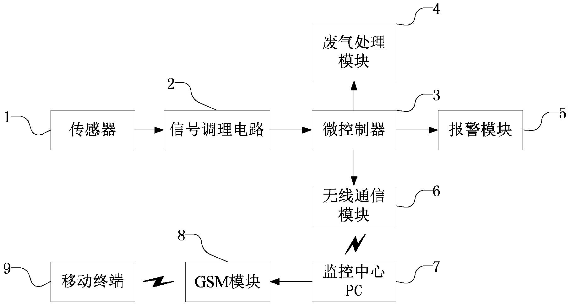
[0033] System embodiment 1: Such as figure 1 As shown, it includes a sensor 1, a signal conditioning circuit 2, a microcontroller 3, an exhaust gas treatment module 4, an alarm module 5, a wireless communication module 6, a monitoring center PC7 and a mobile terminal 9; the sensor 1 is connected to the signal conditioning circuit 2, The signal conditioning circuit 2, exhaust gas treatment module 4, alarm module 5 and wireless communication module 6 are all connected to the microcontroller 3; the microcontroller 3 is wirelessly connected to the monitoring center PC7 through the wireless communication module 6; the monitoring center The PC7 is connected with a GSM module 8, and the monitoring center PC7 is wirelessly connected with the mobile terminal 9 through the GSM module 8.

[0034] The sensor 1 is used to collect data information of exhaust gas to be discharged in real time. The data information includes required information such as the concentration and duration of the...

Embodiment 2

[0048] System embodiment 2: The structure is basically the same as that of system embodiment 1, and the similarities will not be described again, but the difference is:

[0049] The sensor 1 includes 3 groups of sensors, each group of sensors includes 2 galvanic cell type oxidation sensors for detecting oxygen and 2 infrared sensors for detecting hydrocarbons.

[0050] The wireless communication module 6 is a wireless WiFi module. Of course, the wireless communication module may also be other wireless communication devices capable of wireless data transmission.

[0051] The alarm module 5 only includes a voice alarm device.

[0052] The GSM module 8 is integrated on the main board of the monitoring center PC, and is connected with the monitoring center PC7 by wire.

Embodiment 3

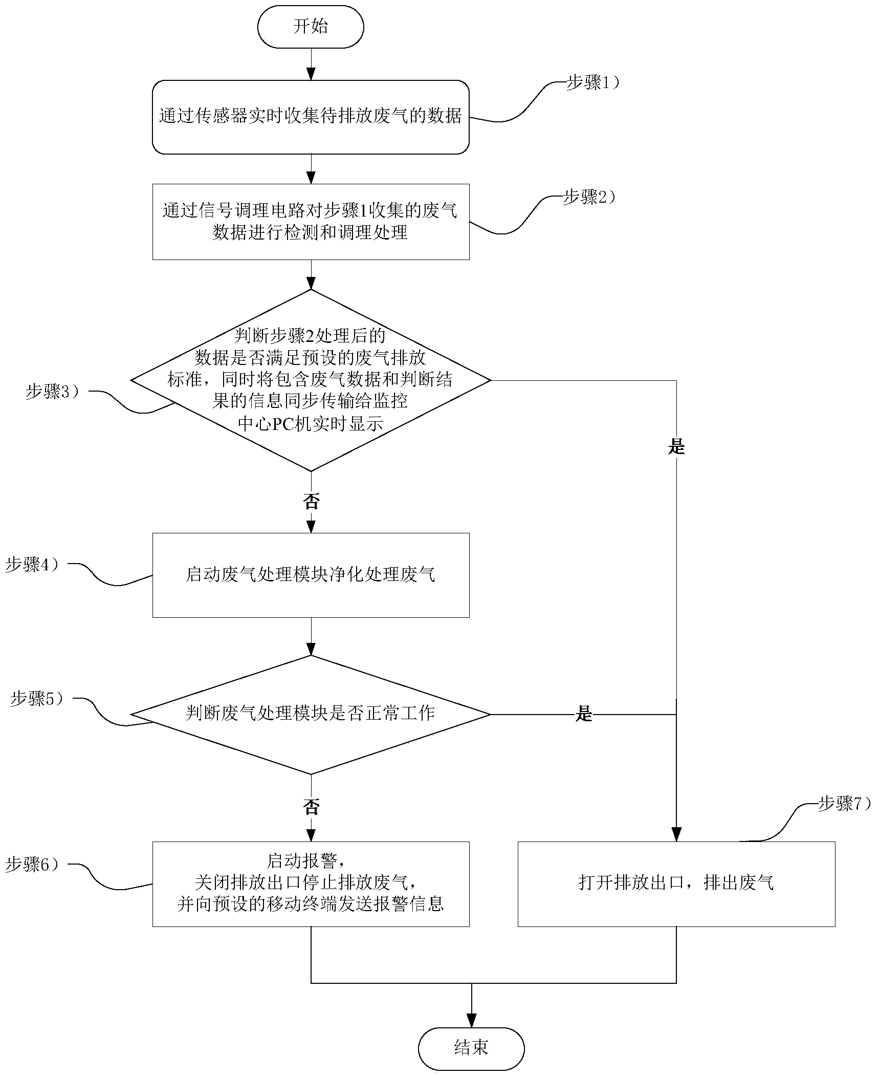
[0054] Such as figure 2 As shown, the exhaust gas purification real-time monitoring method used in the exhaust gas purification real-time monitoring system in the present invention provided by Embodiment 3 of this method includes the following steps:

[0055] Step 1, collect the data of the exhaust gas to be discharged in real time through the sensor;

[0056] Step 2, detecting and conditioning the exhaust gas data collected in step 1 through the signal conditioning circuit;

[0057] Step 3: Judging whether the data processed in step 2 meets the preset exhaust gas emission standards, and synchronously transmitting the information including exhaust gas data and judgment results to the monitoring center PC for real-time display, if yes, go to step 7, otherwise go to step 4 ;

[0058] Step 4, start the waste gas treatment module to purify and treat the waste gas;

[0059] Step 5, judge whether the exhaust gas treatment module is working normally, if so, go to step 7, if not, ...


PUM


Abstract

The invention discloses a waste gas purification real-time monitoring system which comprises a sensor, a signal conditioning circuit, a microcontroller, a waste gas processing module, an alarm module, a wireless communication module, a monitoring center PC and a mobile terminal; the sensor is connected with the signal conditioning circuit; the signal conditioning circuit, the waste gas processing module, the alarm module and the wireless communication module are all connected with the microcontroller; the microcontroller is in wireless connection with the monitoring center PC through the wireless communication module; the monitoring center PC is in wireless connection with the mobile terminal through a GSM module. The invention further discloses a waste gas purification real-time monitoring method. Compared with the prior art, the system and the method, provided by the invention, have the advantages that emission and purification of industrial waste gas can be monitored and reported in real time, and purification of waste gas can be controlled automatically at the same time; besides, in case of abnormal situations, related persons in charge can be reminded promptly for handling through alarming or short messages, so that the effect of being more convenient, rapid and humanized can be achieved; the invention can be widely applied to the field of environmental monitoring.

Description

technical field [0001] The invention belongs to the field of environmental protection monitoring, and in particular relates to a real-time monitoring system and method for waste gas purification. Background technique [0002] As we all know, enterprises will inevitably discharge a large amount of industrial waste gas into the atmosphere during their production process. If these waste gases are discharged directly without meeting the emission standards, it will seriously affect the environment and even cause great harm to human health. Therefore, it is necessary to purify the exhaust gas that does not meet the emission standards before it can be discharged. [0003] However, many enterprises do not have a strong awareness of environmental protection in the production process, especially when the investment in environmental protection directly affects economic benefits, they often pay more attention to economic benefits and ignore the importance of environmental protection. A...

Claims


Application Information

Patent Timeline
Patent Type & Authority Applications(China)
IPC IPC(8): G01N33/00G08C17/02H04L29/06G05B19/042G08B25/10
Inventor 李垣江赵斌张迪明
Owner JIANGSU UNIV OF SCI & TECH
Why Eureka
Try Eureka