
Dominant frequency signal decision circuit and decision method for microwave frequency counter

A microwave frequency and determination circuit technology, applied in the field of testing, can solve the problems of high cost, complex control and compensation circuits, and high frequency bands, and achieve the effects of saving costs, simplifying design, and reducing technical difficulty

Active Publication Date: 2015-01-28
THE 41ST INST OF CHINA ELECTRONICS TECH GRP
View PDF18 Cites 17 Cited by
  • Summary
  • Abstract
  • Description
  • Claims
  • Application Information

AI Technical Summary

Problems solved by technology

[0016] 2. The YIG tuned filter (YTF) is limited by the manufacturing process and materials. It is difficult to make its frequency band very high. At present, the coaxial product is up to 50GHz, and the waveguide product is up to 75GHz, so its application range is difficult to go to the high frequency band. Expansion, even if a very high frequency band can be achieved in the future, affected by factors such as nonlinearity, temperature drift, and hysteresis effects, the control compensation circuit will become more complicated and the cost will become higher

Method used

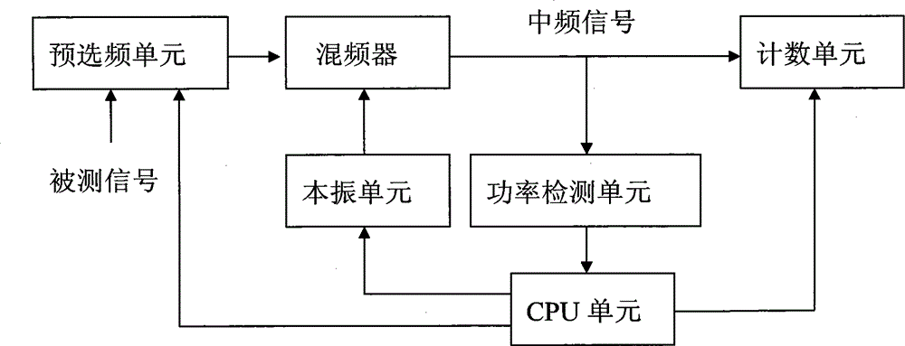

Image

  • Dominant frequency signal decision circuit and decision method for microwave frequency counter
  • Dominant frequency signal decision circuit and decision method for microwave frequency counter
  • Dominant frequency signal decision circuit and decision method for microwave frequency counter

Examples


Embodiment Construction

[0042]The following will clearly and completely describe the technical solutions in the embodiments of the present invention with reference to the accompanying drawings in the embodiments of the present invention. Obviously, the described embodiments are only some, not all, embodiments of the present invention. Based on the embodiments of the present invention, all other embodiments obtained by persons of ordinary skill in the art without making creative efforts belong to the protection scope of the present invention.

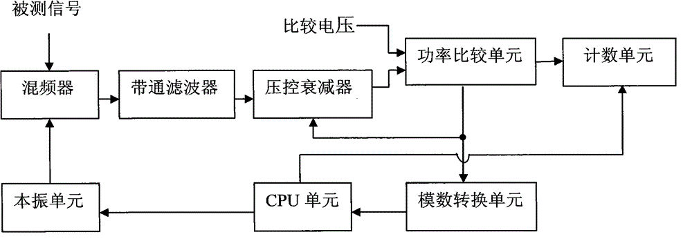
[0043] The present invention designs a main frequency signal determination circuit of a microwave frequency meter, which can determine the main frequency signal in the measurement bandwidth of the microwave frequency meter. The relative power of all signals in the measurement bandwidth can be measured through the power comparison circuit. The signal with the largest relative power is main frequency signal.

[0044] Such as figure 2 As shown, the main frequenc...


PUM


Abstract

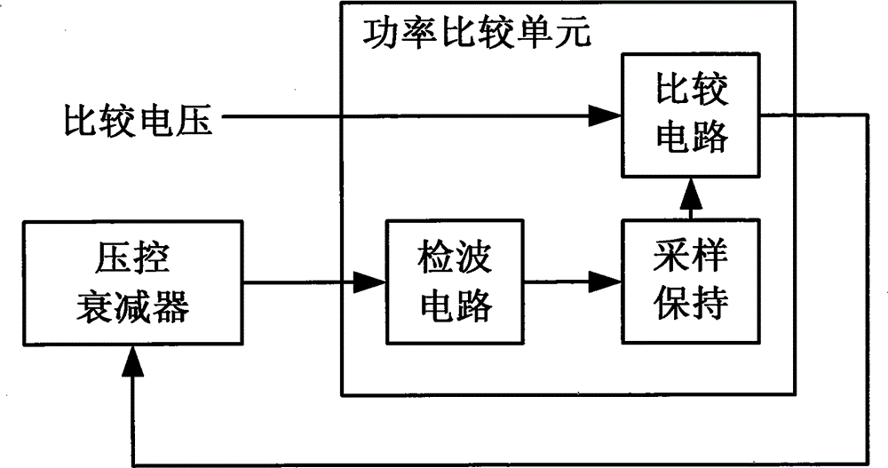
The invention discloses a dominant frequency signal decision circuit and decision method for a microwave frequency counter. The dominant frequency signal decision circuit for the microwave frequency counter comprises a frequency mixer, a local oscillation unit, a band-pass filter, a voltage controlled attenuator, a power comparison unit, a digital-to-analogue conversion unit, a CPU unit and a counting unit. The local oscillation unit provides a frequency mixing local oscillation signal for a frequency meter, and the frequency mixer mixes the measured signal with the local oscillation signal to obtain an intermediate-frequency signal; the band-pass filter filters the intermediate-frequency signal output by the frequency mixer; the voltage controlled attenuator attenuates the power of the intermediate-frequency signal output from the band-pass filter, and the attenuation amplitude is linear to control voltage; the power comparison unit detects the peak of the intermediate-frequency signal input from the voltage controlled attenuator to obtain a peak voltage, samples and holds the peak voltage, compares the sampled and held voltage with a comparison voltage to obtain a control voltage and enables the control voltage to act on the voltage controlled attenuator to attenuate the input intermediate-frequency signal.

Description

technical field [0001] The invention relates to the technical field of testing, in particular to a main frequency signal judging circuit applied to a microwave frequency meter, and also to a main frequency signal judging method applied to a microwave frequency meter. Background technique [0002] With the development of modern electronic technology, in the fields of information communication and military radar, the microwave frequencies used by people are developing towards higher frequency bands, which can reach terahertz or even higher frequency bands. In practical applications, high-frequency signals are mostly obtained by adding a spread spectrum module to the host. The host generates the fundamental wave signal, and after passing through the spread spectrum module, the high-order frequency multiplied signal of the fundamental wave can be generated. The actual high-frequency signal inevitably includes the fundamental signal leaked through the spread spectrum module, the ...

Claims


Application Information

Patent Timeline
IPC IPC(8): G01R23/02
Inventor 凌伟蒙海瑛杜念文张士峰白轶荣
Owner THE 41ST INST OF CHINA ELECTRONICS TECH GRP
Learn More