Power equipment and transmission line malfunction comprehensive online monitoring system

A line fault and power equipment technology, applied in the field of power system fault online monitoring, can solve the problems of real-time upload function of fault information without automatic fault location function, increase the difficulty and time of fault finding, and leave hidden safety hazards in equipment operation, etc., to achieve Improve the fault detection speed and work efficiency, shorten the troubleshooting time, and have the effect of strong signal anti-interference ability

Inactive Publication Date: 2015-01-28
ANSHAN POWER SUPPLY COMPANY OF STATE GRID LIAONING ELECTRIC POWER COMPANY +1
View PDF9 Cites 10 Cited by
  • Summary
  • Abstract
  • Description
  • Claims
  • Application Information

AI Technical Summary

Problems solved by technology

Since the line trips instantaneously and the fault remnants are not obvious, it is very difficult to inspect the fault point. If the fault point cannot be inspected within a period of time, it will leave a safety hazard for the operation of the equipment
[0004] Overheating faults of power equipment and power-frequency grounding faults of transmission lines are high-risk and prone to failures. Traditional power equipment temperature monitoring and transmission line fault finding methods do not have the functions of automatic fault location and real-time upload of fault information. Once a fault occurs, manual search along the line is required. , which increases the difficulty and time of fault finding. At present, there is no comprehensive online monitoring system for overheating faults of power equipment and power frequency grounding faults of transmission lines at the same time.

Method used


Image

  • Power equipment and transmission line malfunction comprehensive online monitoring system
  • Power equipment and transmission line malfunction comprehensive online monitoring system
  • Power equipment and transmission line malfunction comprehensive online monitoring system

Examples


Embodiment Construction

[0029] The specific technical solutions of the present invention will be further described in detail below in conjunction with the accompanying drawings.

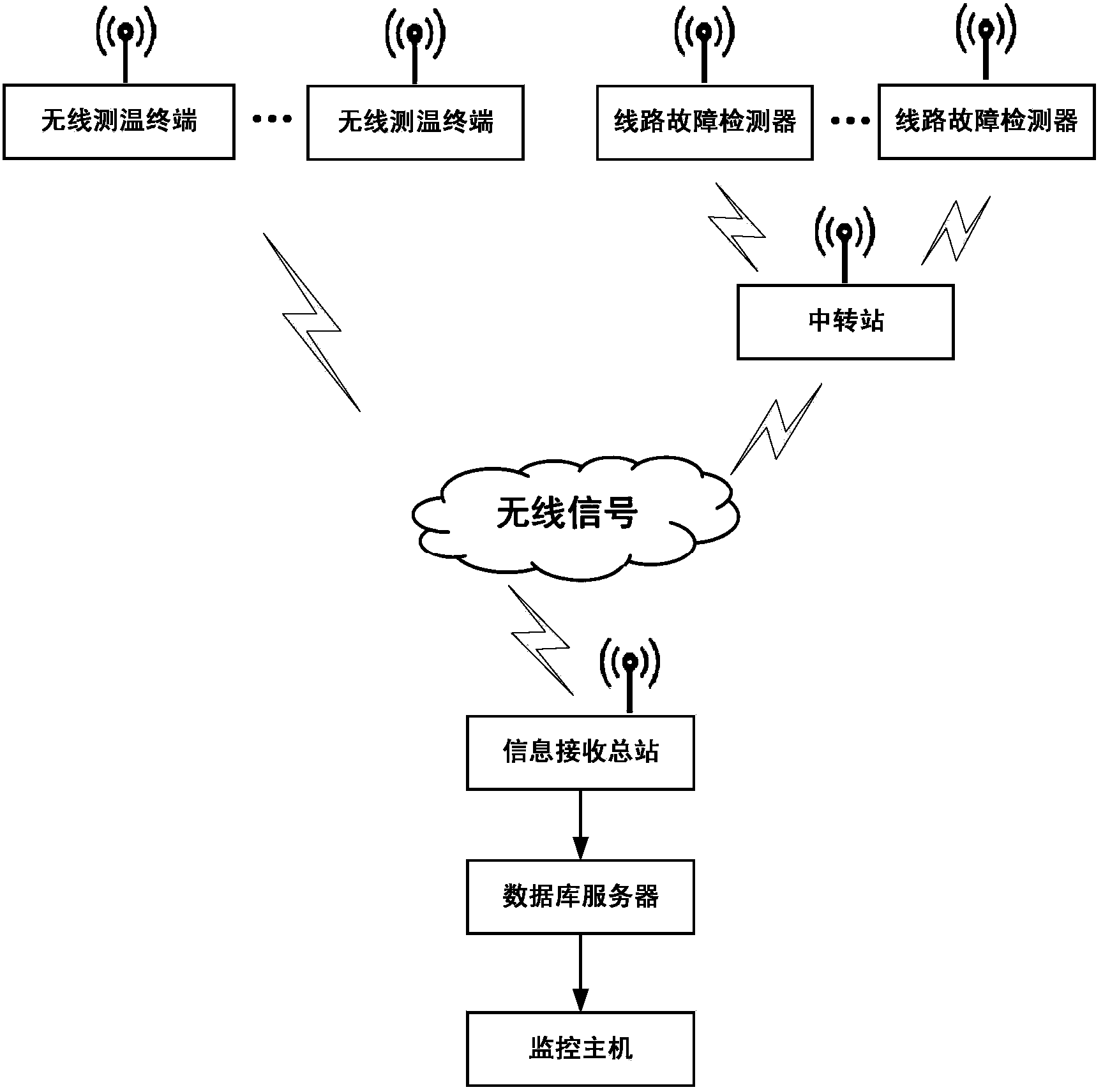
[0030] See figure 1 , a comprehensive online monitoring system for power equipment and transmission line faults, including a wireless temperature measurement terminal, a line fault detector, a transfer station, an information receiving general station, a database server, and a monitoring host. The wireless temperature measurement terminal is wirelessly connected to the information receiving terminal through the built-in wireless communication module, and the line fault detector is wirelessly connected to the transfer station and the information receiving terminal through the built-in wireless communication module, and the information receiving terminal is connected to the database server , the database server is connected to the monitoring host.

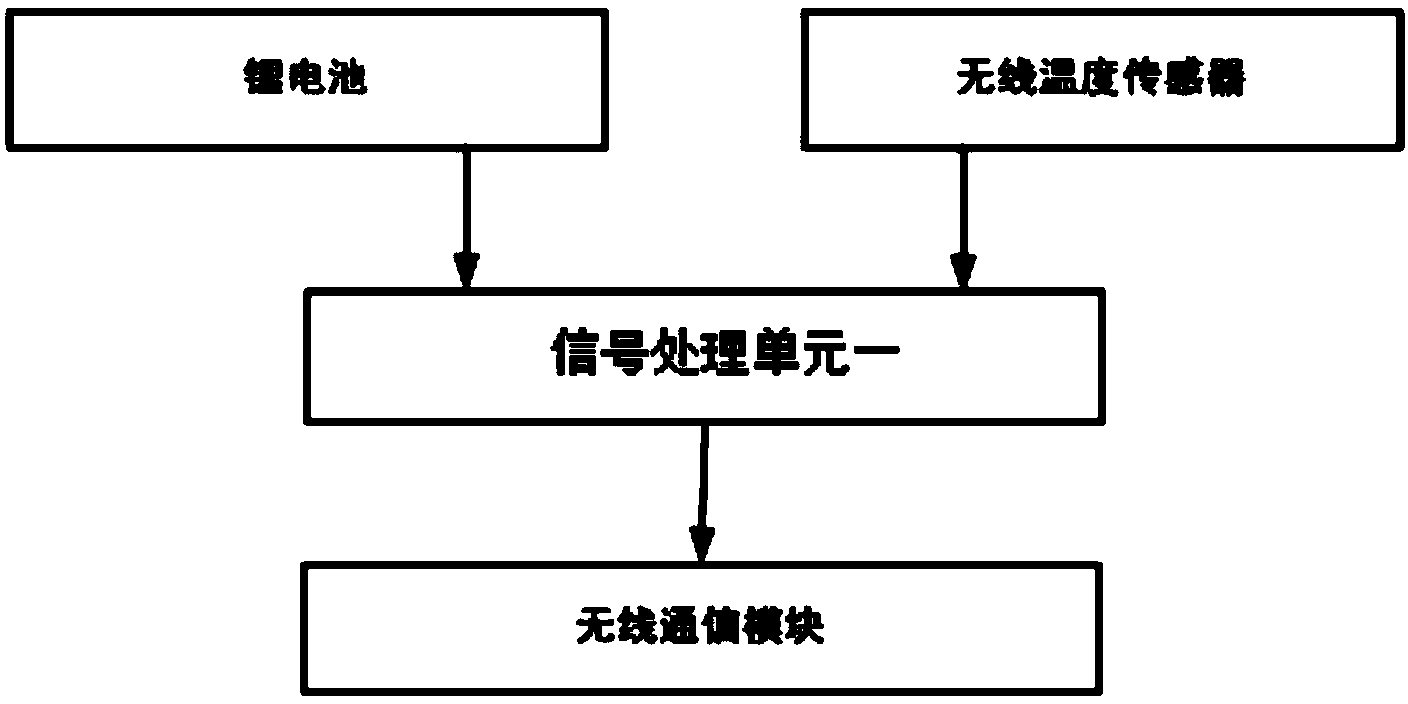
[0031] See figure 2 , one of the wireless temperature measurement terminal...


PUM


Abstract

The invention discloses a power equipment and transmission line malfunction comprehensive online monitoring system which comprises a wireless temperature measuring terminal, a line malfunction detector, a transfer station, an information receiving main station, a database server and a monitoring host. The wireless temperature measuring terminal is wirelessly connected with the information receiving main station through a built-in wireless communication module, the line malfunction detector is wirelessly connected with the information receiving main station through a built-in wireless communication module and the transfer station, and the information receiving main station is connected with the database server which is connected with the monitoring host. The system can monitor and upload power equipment temperature rise standard exceeding and transmission line ground fault information in real time, quickly locate line fault sections and fault branches, shorten fault clearing time and improve safety and reliability of power equipment and transmission lines.

Description

technical field [0001] The invention relates to the field of on-line fault monitoring of power systems, in particular to a comprehensive on-line fault monitoring system for power equipment and transmission lines. Background technique [0002] During the long-term operation of power system equipment, problems such as surface oxidation and corrosion, loosening of fastening bolts, and aging of contacts and busbar connections often occur, resulting in overheating of equipment and even serious accidents. However, there is exposed high voltage in the switchgear, and the space is closed and narrow, so manual inspection and temperature measurement cannot be carried out. The traditional temperature measurement method cannot effectively solve this problem. [0003] my country's transmission lines are distributed in a network structure, with many branches, and most areas have complex terrains. The number of tripping accidents of transmission lines caused by natural disasters such as li...

Claims


Application Information

Patent Timeline
Patent Type & Authority Applications(China)
IPC IPC(8): G01R31/08
CPCY04S10/52
Inventor 张朝龙
Owner ANSHAN POWER SUPPLY COMPANY OF STATE GRID LIAONING ELECTRIC POWER COMPANY
Why Eureka
Try Eureka