Multichannel receiver real-time calibration device and calibration and error compensation method

A calibration device and error compensation technology, applied in the radar field, can solve problems such as limited surveying and mapping bandwidth, difficulty in distortion compensation, difficulty in system compensation, etc., achieve strong real-time performance and flexibility, solve receiving problems, and have high automation

Active Publication Date: 2015-01-28
INST OF ELECTRONICS CHINESE ACAD OF SCI
View PDF4 Cites 38 Cited by
  • Summary
  • Abstract
  • Description
  • Claims
  • Application Information

AI Technical Summary

Problems solved by technology

This scheme is very effective for LFM signals under certain conditions, but it also has the following problems: (1) Distortion compensation is difficult: due to the introduction of the time-frequency conversion link, the corresponding time-frequency conversion distortion is brought, when the target moves or the frequency modulation itself When the vibration trigger time changes, the influence of this distortion changes accordingly, showing the nature of shifting, which brings great difficulty to the system compensation; (2) The bandwidth of surveying and mapping is limited: in order to reduce the signal bandwidth, deskewing The processing is at the expense of the surveying and mapping bandwidth, that is to say, if the surveying and mapping bandwidth is required to be wide, the purpose of reducing the signal bandwidth cannot be achieved after deskewing
[0010] For the synchronization error between channels, the existing technology is applicable when the sampling rate of the A/D device is low. Once high-speed A/D is involved, such as the intermediate frequency sampling rate of the receiving c

Method used


Image

  • Multichannel receiver real-time calibration device and calibration and error compensation method
  • Multichannel receiver real-time calibration device and calibration and error compensation method
  • Multichannel receiver real-time calibration device and calibration and error compensation method

Examples


Embodiment Construction

[0060] In order to make the object, technical solution and advantages of the present invention clearer, the present invention will be further described in detail below in conjunction with specific embodiments and with reference to the accompanying drawings.

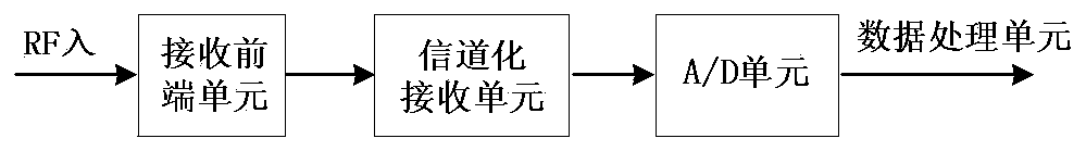
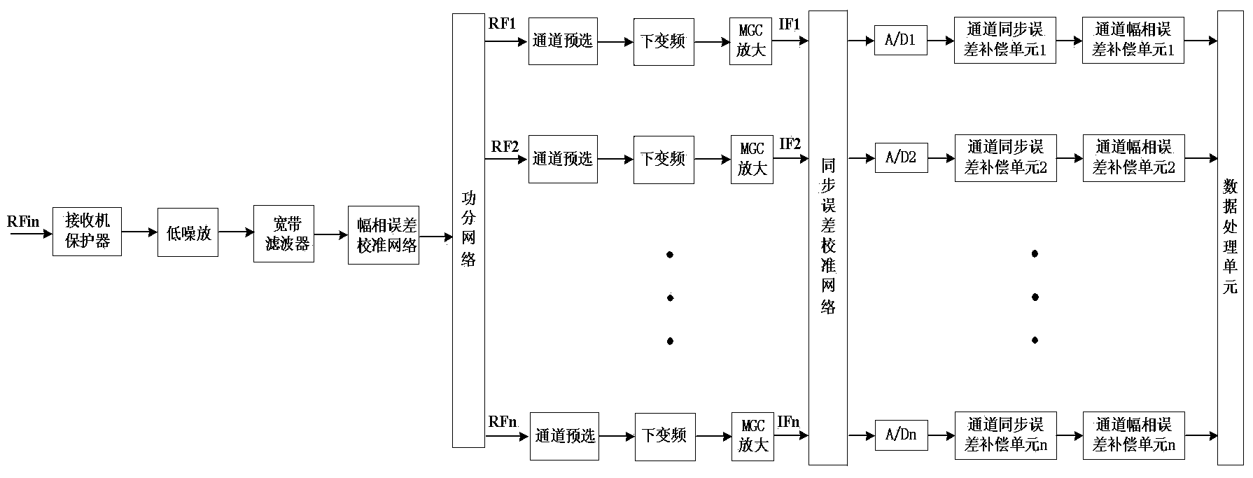
[0061] Under the current technical conditions, in order to improve the range resolution of systems such as synthetic aperture radar, multi-channel synthesis is one of the main technical means currently used. But this method needs to focus on solving two problems, one is the synchronization problem of multi-channel A / D, and the other problem is the amplitude-phase distortion problem of multi-channel.

[0062] Aiming at the two main error components of multi-channel received signals—synchronization error and amplitude-phase error, the present invention uses a step-by-step method to decompose the calibration into two effective steps, which correspond to the synchronization error calibration and amplitude-phase error calibrati...


PUM


Abstract

The invention discloses a multichannel receiver real-time calibration device. The multichannel receiver real-time calibration device comprises a synchronous error calibration device used for carrying out real-time synchronous calibration and error compensation on a multichannel receiver, and an amplitude-phase error calibration device used for carrying out real-time amplitude-phase calibration and error compensation on the multichannel receiver. The invention further discloses a multichannel receiver real-time calibration method. The multichannel receiver real-time calibration device and method achieve comprehensive error calibration, real-time synchronous calibration and real-time amplitude-phase calibration can be carried out on the multichannel receiver at the same time through the integrated structure, high real-time performance and flexibility are achieved, the degree of automation is high, the error calibration is carried out on the whole system working process, the system calibration process can be finished only by making corresponding selection on a system control interface without need of any wiring or hardware change, operation is easy, use is rapid, influence on a receiving channel from environment conditions and device characteristics can be compensated accurately, and large bandwidth signals can be received effectively.

Description

technical field [0001] The invention belongs to the technical field of radar, and more specifically relates to a multi-channel receiver real-time calibration device and a calibration and error compensation method. Background technique [0002] Because synthetic aperture radar (SAR) can image the ground all day and all day long, and has the ability to penetrate vegetation and camouflage, it is widely used in military reconnaissance, disaster monitoring, resource exploration, terrain surveying and other fields, and is favored by the world. Countries are paying more and more attention. With the continuous development of synthetic aperture radar technology and the continuous expansion of application fields, the requirements for radar performance are getting higher and higher. Among them, resolution, as one of the core technical indicators of synthetic aperture radar, has been promoted to a higher position. [0003] The improvement of distance resolution depends on the improveme...

Claims


Application Information

Patent Timeline
IPC IPC(8): G01S7/40
CPCG01S7/40
Inventor 郭征王岩飞周以国赵风华李和平
Owner INST OF ELECTRONICS CHINESE ACAD OF SCI
Why Eureka
Try Eureka