Liquid crystal element multiple eye telescoping bionic imaging detection chip

A chip and liquid crystal technology, applied in the field of imaging detection, can solve the problems of slow response, small structure size, limited imaging modulation ability, etc., and achieve the effects of convenient use, convenient connection and good adaptability

Active Publication Date: 2015-01-28
HUAZHONG UNIV OF SCI & TECH
View PDF5 Cites 4 Cited by
  • Summary
  • Abstract
  • Description
  • Claims
  • Application Information

AI Technical Summary

Problems solved by technology

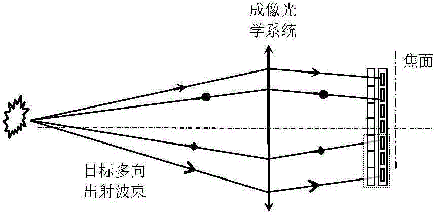
[0003] The existing bionic compound eye structures based on the coupling of area array micro-optical imaging structures and photosensitive arrays are all based on arrayed refractive or diffractive microlenses with fixed optical imaging capabilities. Typical defects include: (1) Conventional microlenses do not have the ability to characterize optical imaging There is a significant gap between the adjustment ability of multiple parameters, such as focal length, focal spot brightness and size, focal depth, point spread function and field of view, and the adjustable biological compound eye, and the adaptability to the environment and the target is poor; (2) The unit imaging microlens as a sub-aperture can only match a limited-scale sub-photosensitive array, and the compound eye target image constructed by further compression of the sub-aperture has a small structural size, low spatial resolution, low image clarity and contrast, and poor image quality; ( 3) The target image constructed based on the compound eye (sub-aperture) image and the image data rearrangement according to the scale of the microlens, although the spatial resolution is significantly increased, the structural size, clarity and contrast of the target image are significantly improved, but it is limited by The invariance of the optical ability of the microlens also shows poor adaptability to the environment and the target; (4) The zoom imaging is carried out through the mechanical movement between the converging or diverging microlens arrays arranged in cascade, which needs to be matched with complex and precise driving devices , the zoom operation can only be carried out in a fixed order, the response is slow, the process is long, and the inertia is large, and it is impossible to perform fast electronically controlled cut-in or jump of any optical state, and the imaging modulation capability is extremely limited; Compound eye structure coupled with lens and photosensitive array

Method used


Image

  • Liquid crystal element multiple eye telescoping bionic imaging detection chip
  • Liquid crystal element multiple eye telescoping bionic imaging detection chip
  • Liquid crystal element multiple eye telescoping bionic imaging detection chip

Examples


Embodiment Construction

[0023] In order to make the object, technical solution and advantages of the present invention clearer, the present invention will be further described in detail below in conjunction with the accompanying drawings and embodiments. It should be understood that the specific embodiments described here are only used to explain the present invention, not to limit the present invention. In addition, the technical features involved in the various embodiments of the present invention described below can be combined with each other as long as they do not constitute a conflict with each other.

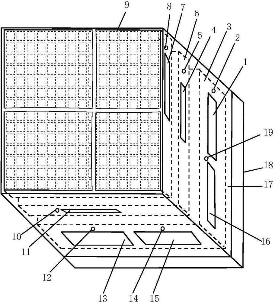
[0024] Such as figure 1 As shown, the liquid crystal-based multi-eye telescopic imitation imaging detection chip of the present invention includes: a chip housing 17, a metal support and heat dissipation plate 18, and a multi-eye telescopic imaging detection structure.

[0025] The multi-eye telescopic imaging detection structure is set in the chip housing 17 and includes a drive control and im...


PUM


Abstract

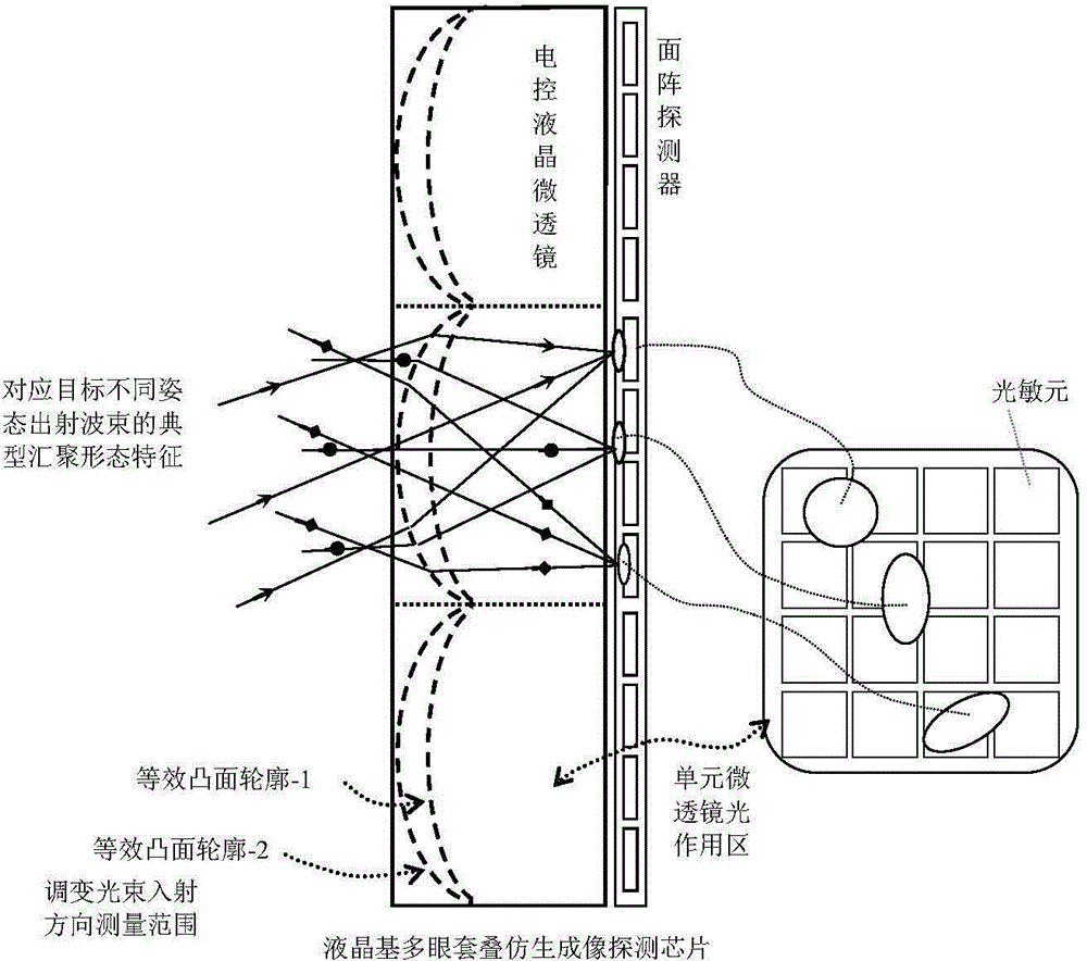
The invention discloses a liquid crystal element multiple eye telescoping bionic imaging detection chip. The liquid crystal element multi-eye telescoping bionic imaging detection chip comprises a multiple eye telescoping imaging detection framework, wherein the multiple eye telescoping imaging detection framework comprises a drive control and image preprocessing module, an area array visible light detector and an area array electronic control liquid crystal spotlight micro lens, which are coaxially arranged in sequence, the area array electronic control liquid crystal spotlight micro lens comprises m*m unit micro lens, m is a positive integer, the area array visible light detector is divided into m*m sub-area-array visible light detectors, each sub-area-array visible light detector comprises m*m photosensitive elements, and the area array electronic control liquid crystal spotlight micro lens is used to receive a target light wave, and discretely segments the target light wave onto the photosensitive elements corresponding to the different sub-area-array visible light detectors in the area array visible light detector. The liquid crystal element multiple eye telescoping bionic imaging detection chip has the advantages of being compact in structure, convenient to use, easy to couple with a routine imaging optics system, good in target and environment adaptability and the like.

Description

technical field [0001] The invention belongs to the technical field of imaging detection, and more specifically relates to a liquid crystal-based multi-eye telescopic bionic imaging detection chip. Background technique [0002] So far, the technology of synchronously acquiring multi-pose images of targets through bionic compound eyes has developed rapidly, such as typical light field cameras and panoramic cameras stitching multiple bionic compound eyes. At present, through in-depth analysis, function mining and expansion of the visual mechanism of the arrayed imaging of insect compound eyes, based on the rearrangement of compound eye images, the structure is clearer, the structure size is doubled, and the target shape is more complete and rich. The target image, making full use of the high spatial frequency compound eye image to enhance or even achieve super-resolution imaging detection, has become a research and development hotspot of visual bionic imaging technology, and h...

Claims


Application Information

Patent Timeline
IPC IPC(8): H01L27/146G01J5/10
Inventor 张新宇雷宇罗俊佟庆桑红石张天序谢长生
Owner HUAZHONG UNIV OF SCI & TECH
Why Eureka
Try Eureka