Motor iron core with sealing structure and combination device

A sealing structure and iron core technology, applied in the direction of electromechanical devices, electric components, magnetic circuit shape/style/structure, etc., can solve problems such as debonding, large difference in elastic modulus, damage to stator and rotor insulation, etc., to prevent the loss of paint Effect

Active Publication Date: 2015-01-28
XINJIANG GOLDWIND SCI & TECH
View PDF2 Cites 3 Cited by
  • Summary
  • Abstract
  • Description
  • Claims
  • Application Information

AI Technical Summary

Problems solved by technology

[0004] 2. Technical description and existing defects of varnish insulation treatment
It not only affects the loss of paint, but also affects the amount of paint hanging on the inner and outer surfaces of the second dipped paint core
The amount of paint hanging is small, so there is no need to scrape the paint, but the loss of paint will inevitably cause gaps between the insulation in the tank, resulting in hidden dangers of water ingress and moisture inhalation that will damage the insulation
[0007] However, the slot wedge structure of the prior art does not have effective sealing measures, although it is conducive to the entry of paint, it cannot prevent the loss of paint when dripping paint
[0008] 3. Insulation defects caused by thermal expansion of the existing slot wedge and slot insulating porous medium
[0012] 4. Defect analysis of existing slot wedges
[0014] 1) The internal contradiction shown in the vacuum pressure impregnation process has shown that although the existing slot wedge structure is conducive to the entry of paint, it cannot prevent the loss of paint along the existing slot wedge when the paint is dripped after the first dipping
[0015] 2) In the prior art, when slot wedges are used to fix the coils in the tooth slots, since the tooth laminations of the core slot and the slot wedge are made of different materials, the elastic modulus differs greatly. The interface of the bonding layer formed by insulating varnish (or glue) between the tooth laminations will appear "debonding", moisture and water will naturally enter the groove to destroy the insulation, and even the loss of damaged medium (liquid)
However, this technique cannot ensure that the bonding layer interface between the slot wedge and the iron core slot is firm, and cannot prevent moisture and water from naturally entering the slot along the bonding layer fracture gap to damage the insulation.
And this technology is used in wind turbines in the natural environment. A large number of flocs and ferromagnetic substances appear around the surface of the magnetic slot wedge material, and even block the air gap and damage the insulation between the stator and rotor.

Method used


Image

  • Motor iron core with sealing structure and combination device
  • Motor iron core with sealing structure and combination device
  • Motor iron core with sealing structure and combination device

Examples


Embodiment 1

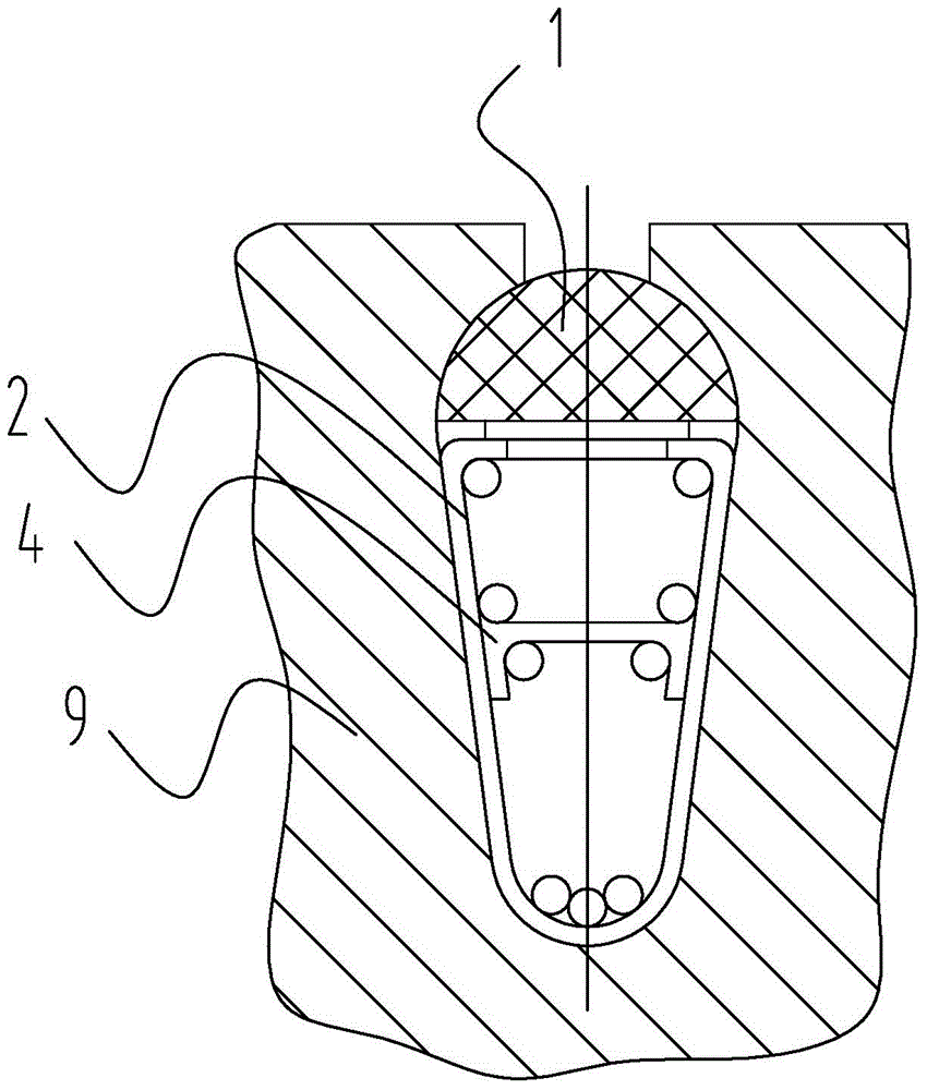
[0068] The embodiment of the present invention improves the prior art slot wedge, adds a sealing structure on the basis of the existing slot wedge, and proposes a motor slot wedge with a sealing structure. A groove is arranged on the outer wall of the slot wedge, and a thermal expansion material is arranged in the groove, and the thermal expansion material contacts the inner wall of the tooth groove of the iron core after being heated and expanded. Among them, the thermally expandable material is preferably an elastic thermally expandable material, and specifically, thermally expandable glass mat or thermally expandable rubber can be used.

[0069] The specific structure of the groove and the expansion material will be described in detail below in conjunction with the accompanying drawings, and for the convenience of description, the relevant structures will be defined and described. The part between the teeth 9 of the core is called the cogging, and the cogging of the core is...

Embodiment 2

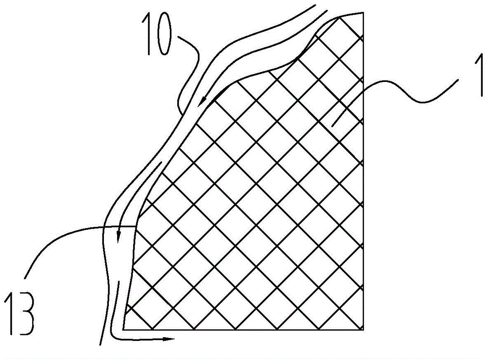
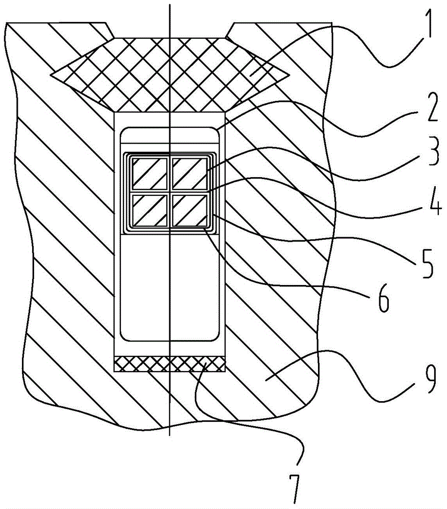
[0085] The solution provided by this embodiment is a motor core with a sealed structure, such as Figure 31 and Figure 32 shown, as a pair Figure 5 and Figure 6 The improvement of the existing iron core structure shown, the difference between this embodiment and the first embodiment is that the thermal expansion material is not arranged in the groove of the slot wedge, but directly arranged at the notch of the core tooth groove . In this embodiment, the inner wall at the bottom of the groove of the iron core slot is stepped (different from the prior art), the thermal expansion material is abutted against the surface of the lower step, and the thickness of the expansion material is higher than that between the lower step and the upper step. height difference between them. Such as Figure 32 After being heated and expanded, the heat-expandable material extends along the surface of the upper step to fill the gap between the surface of the upper step and the bottom side of...


PUM


Abstract

The invention provides a motor iron core with a sealing structure and a combination device. A structure of the motor iron core is that the internal wall at the bottom of a notch of an iron core tooth groove is in a stair shape; thermal expansion materials are abutted to the surface of a lower layer stair; the thickness of the expansion materials is higher than the altitude difference between the lower layer stair and an upper layer stair. According to the technical scheme, the internal wall at the bottom of a notch of the iron core tooth groove is machined to be in the stair shape, the thermal expansion materials are arranged at the stair positions, then a sealing structure is formed between the slot wedge and the internal wall of the tooth groove of the iron core, moisture is prevented from entering into the interior of the tooth grove of the iron core and damaging an insulating structure, and paint loss after vacuum pressure impregnation is blocked.

Description

technical field [0001] The invention relates to a motor core, in particular to a motor core with a sealing structure and a combination device of the motor core and a slot wedge. Background technique [0002] 1. Description of the insulation structure of the motor and the structure of the slot wedge [0003] In the production process of the motor, it is necessary to open slots on the iron core of the stator or rotor, and arrange coils in the slots, and then install various shapes of slot wedges on the slots of the slots to fix the coils in the slots. Commonly used materials for making slot wedges are: 3020-3023 (the number is the type of insulating material) phenolic laminated cardboard; bamboo (after insulation treatment, reaching insulation grade E); 3230 phenolic laminated glass cloth board, 3231 aniline phenolic Laminated glass cloth board (after insulation treatment, reach insulation grade B); 3240 epoxy phenolic laminated glass cloth board (after insulation treatment, ...

Claims


Application Information

Patent Timeline
Patent Type & Authority Applications(China)
IPC IPC(8): H02K1/06H02K3/34H02K15/10
CPCH02K1/165H02K1/265H02K3/34H02K3/44H02K3/487
Inventor 王栋马盛骏刘承前赵祥
Owner XINJIANG GOLDWIND SCI & TECH
Why Eureka
Try Eureka