
ROF radio frequency switching system and radio frequency switching method

A technology of radio frequency switching and radio frequency, which is applied in the direction of transmission system, electromagnetic wave transmission system, multiplexing system selection device, etc. It can solve the problem of unbalanced traffic flow, increased system maintenance work and instability, and manual methods cannot meet dynamic requirements. Mobility requirements and other issues, to achieve the effect of reducing regional access differences and maximizing wireless bandwidth

Inactive Publication Date: 2015-01-28
SHENZHEN HIRISUN TECH
View PDF6 Cites 3 Cited by
  • Summary
  • Abstract
  • Description
  • Claims
  • Application Information

AI Technical Summary

Problems solved by technology

[0002] At present, in the direction of RF signal routing in the ROF system, each RF signal circuit is basically directly connected to the RF optical transmitter, or multiple RF signals After processing by the splitter combiner, the mixed RF signal line is connected to the RF optical transmitter. In this mode, the signal that can be accepted by each light direction or the coverage of the antenna terminal is a constant set mode. It is impossible to dynamically adjust the access direction of radio frequency signals. Specifically, there are some problems as follows:
[0004]2. Some devices can be connected manually or the direction of the radio frequency circuit can be changed by using a dial switch, but this also greatly increases the maintenance work and instability of the system sex
[0005]3. When the flow of access users in several areas causes unbalanced traffic movement, the manual method cannot meet the dynamic mobility requirements

Method used


Image

  • ROF radio frequency switching system and radio frequency switching method

Examples


Embodiment Construction

[0019] Specific embodiments of the present invention will be described in detail below in conjunction with the accompanying drawings.

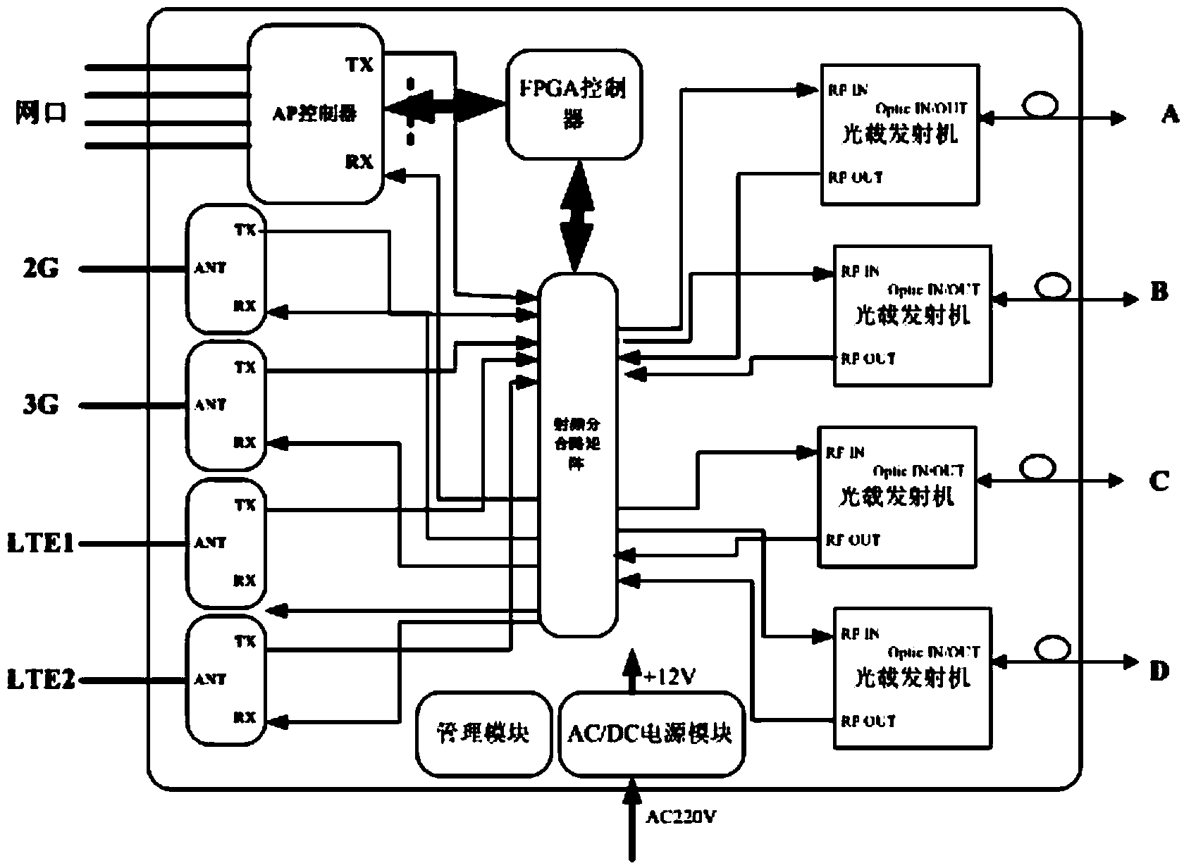
[0020] At present, in the ROF system of the existing technology, in the routing direction of the RF signal, each RF signal circuit is basically directly connected to the RF optical transmitter, or multiple RF signals are processed by a splitter combiner and then connected by a mixed RF signal line. To the radio frequency optical transmitter, the AP controller and 2G / 3G / LTE module are connected to the radio frequency splitting and combining matrix to connect to multiple optical transmitters, and each optical transmitter is connected to the user area.

[0021] Such as figure 1 As shown, the ROF radio frequency switching system involved in the present invention includes an AP controller module, a radio frequency division and combination matrix module, a power supply module, a ROF optical wireless optical transceiver module, an FPGA controller mod...


PUM


Abstract

The invention discloses a ROF radio frequency switching system and a radio frequency switching method. The radio frequency switching system comprises a radio frequency shunting / combining matrix module, an AP controller module, a power module, a ROF (radio over fiber) optical transceiver module, and a FPGA controller module, wherein the radio frequency shunting / combining matrix module is connected with the ROF optical transceiver module and the power module and the FPGA controller module is a field programmable gate array module and is connected with the radio frequency shunting / combining matrix module so that the dynamic balance of the radio frequency switching of the system is realized. Through the intelligent identification and programming of the FPGA controller module, different control modes and control parameters are combined to dynamically adjust access directions of radio frequency signals, the reallocation of the radio frequency signals is realized, the regional access difference is reduced and the balancing access is finally achieved, and the WiFi wireless bandwidth shared by a user is maximized.

Description

technical field [0001] The invention relates to an ROF radio frequency switching system and a radio frequency switching method. Background technique [0002] At present, in the route selection direction of the RF signal in the ROF system, each RF signal circuit is basically directly connected to the RF optical transmitter, or multiple RF signals are processed by a splitter combiner and then connected to the RF by a hybrid RF signal line. Optical transmitter, in this mode, the signal that can be accepted by each light direction or the coverage area of ​​the antenna terminal is a constant set mode, and the access direction of the radio frequency signal cannot be dynamically adjusted. Specifically, There are some problems as follows: [0003] 1. When there are different numbers of access users in each area at the far end of each optical transmitter direction, if there are too many access users in one area, the capacity is insufficient, and many users cannot communicate; while ...

Claims


Application Information

Patent Timeline
IPC IPC(8): H04W16/10H04W28/08H04W28/26H04B10/2575H04Q11/00
CPCH04B10/25759H04W28/08
Inventor 龙腾
Owner SHENZHEN HIRISUN TECH
Learn More