A method for improving maneuvering efficiency based on position change of aileron connection joints

A technology for connecting joints and operating efficiency, applied in the aerospace field, can solve the problems of increasing aileron weight, high airflow speed, aileron reverse effect, etc., to improve aileron control efficiency, avoid stuck phenomenon, and increase processing costs. Effect

Active Publication Date: 2020-11-10
BEIJING AERONAUTIC SCI & TECH RES INST OF COMAC +1
View PDF7 Cites 0 Cited by
  • Summary
  • Abstract
  • Description
  • Claims
  • Application Information

AI Technical Summary

Problems solved by technology

Due to the high airflow velocity of high-speed aileron, the control force is increased, and the stiffness of the aileron structure near the wing root is also strengthened. However, the roll arm is small, so the increase in the control balance moment is offset
[0005] Conventional ailerons are placed on the outside of the wing, with a long span and short chord. When the angle of attack is large or the incoming flow velocity is high, the control surface is easily deformed, resulting in the problem of aileron reverse effect. Therefore, the adjustment of the airfoil structure The size increases the stiffness of the aileron, but it will increase the weight of the aileron; the aileron fixed by multiple joints can also be used. If the wing is deformed during flight, the axis of the aileron shaft will also be bent, which will affect the flexibility of manipulation. sex, and even stagnation

Method used


Image

  • A method for improving maneuvering efficiency based on position change of aileron connection joints
  • A method for improving maneuvering efficiency based on position change of aileron connection joints
  • A method for improving maneuvering efficiency based on position change of aileron connection joints

Examples


Embodiment 1

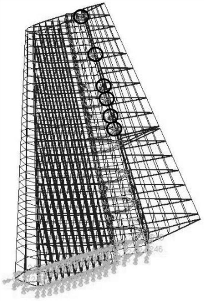
[0048] Embodiment 1: working condition one

[0049] Using the above method, I won’t go into details here. The specific layout scheme is as follows: Figure 5 shown.

Embodiment 2

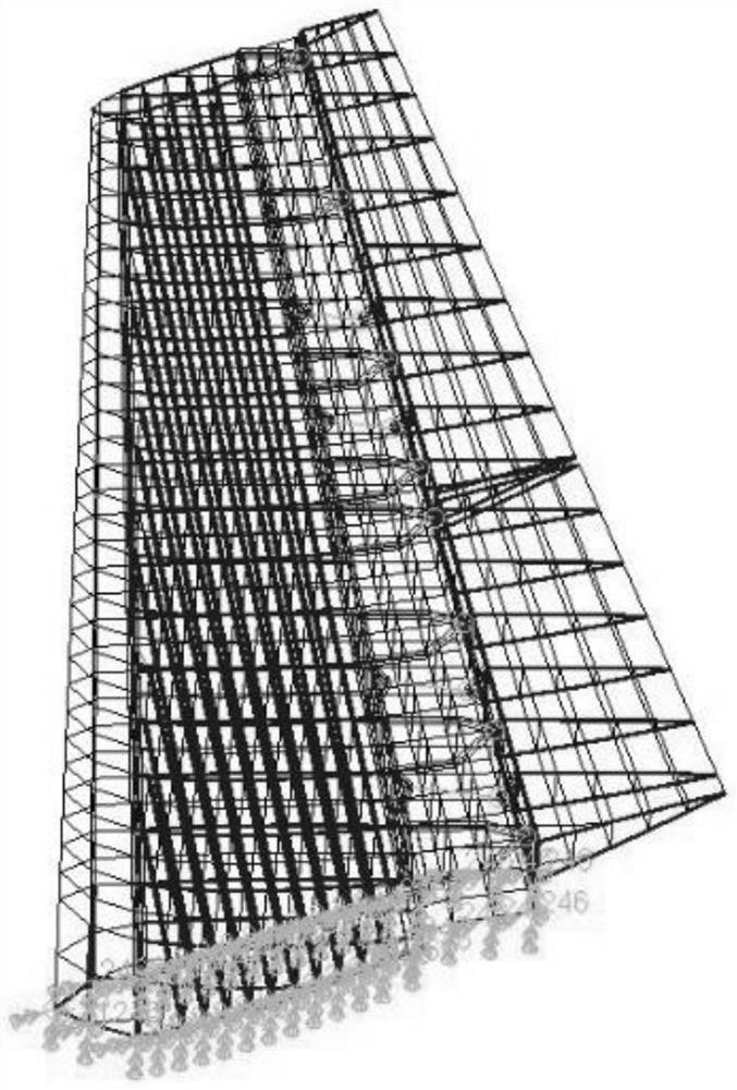
[0050] Example 2: working condition two

[0051] Using the above method, I won’t go into details here. The specific layout scheme is as follows: Figure 6 shown.

Embodiment 3

[0052] Embodiment 3: working condition three:

[0053] Using the above method, I won’t go into details here. The specific layout scheme is as follows: Figure 7 shown.

[0054] See the following table for the different operating efficiencies of the three working conditions:

[0055] Table 1 Comparison table of operating efficiency

[0056] Condition Operating efficiency η(%) one 34.58 two 88.29 three 71.25


PUM


Abstract

An operation efficiency increasing method based on a position change of an aileron connector is provided. In the method, a connector of an aileron is adopted to fix an aileron surface rotated by a servo, and the hinge position of another connector is adjusted according to the speed of incoming flow or an angle of attack, thus increasing connection rigidity of an aileron surface to allow loads on the aileron surface to be redistributed, and reducing elastic deformation of the aileron surface so as to increase the operation efficiency of the aileron. Abovementioned situations can be avoided under the premise of not increasing an operating mechanism, and the cost is reduced. The two connectors are adopted in a wing-aileron connection, the position of one of the connectors changes, and contactof the connectors is controlled by a relay. According to different flight conditions, the position of the wing-aileron connector changes to change wing-aileron connection (support) rigidity so as toredistribute (optimize) loads on the aileron surface, and aileron deformation is reduced to increase the aileron operation efficiency.

Description

technical field [0001] The invention belongs to the field of aerospace technology, and in particular relates to a method for improving control efficiency based on position changes of aileron connecting joints. Background technique [0002] The aileron is a small movable airfoil mounted on the outside of the trailing edge of the wing tip (see figure 1 ), which is the main operating rudder surface of the aircraft. By manipulating the ailerons to generate a rolling moment, the aircraft can perform rolling maneuvers. Aileron trim is to add a trim function to the aileron control system, so as to reduce the pilot's operating burden and improve flight performance during aileron control. Its main function is to control the rotation of the aircraft fuselage around the longitudinal axis, so as to realize the rolling of the aircraft. The left and right ailerons are symmetrically installed on the left and right wings, and their deflection is controlled by the pilot. The left and righ...

Claims


Application Information

Patent Timeline
Patent Type & Authority Patents(China)
IPC IPC(8): B64C9/02G06F30/15
CPCB64C9/02G06F30/15Y02T50/30
Inventor 邱菊徐吉峰邓志吴晓光
Owner BEIJING AERONAUTIC SCI & TECH RES INST OF COMAC
Why Eureka
Try Eureka