Metal-wire-loading type electromagnetic wave absorption structure improving performances of oblique incidence
A technology of electromagnetic wave absorption and metal wire, which is applied in the direction of electrical components, magnetic field/electric field shielding, etc., can solve the problems of thick thickness, few researches on the wave absorption performance of electromagnetic wave absorbing structures, and good wave absorbing effect at the same time, so as to achieve improvement The effect of microwave absorption performance, simple and mature manufacturing process, and low cost
- Summary
- Abstract
- Description
- Claims
- Application Information
AI Technical Summary
Problems solved by technology
Method used
Image
Examples
Embodiment 1
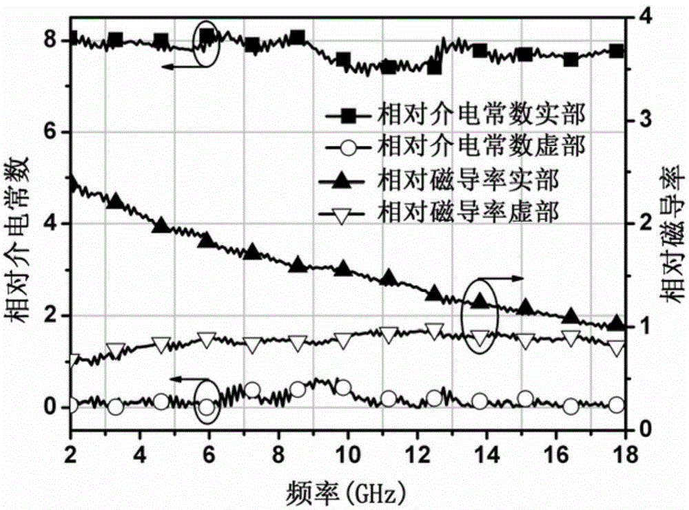
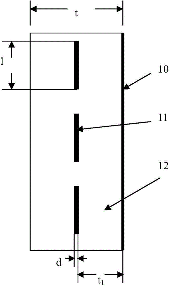
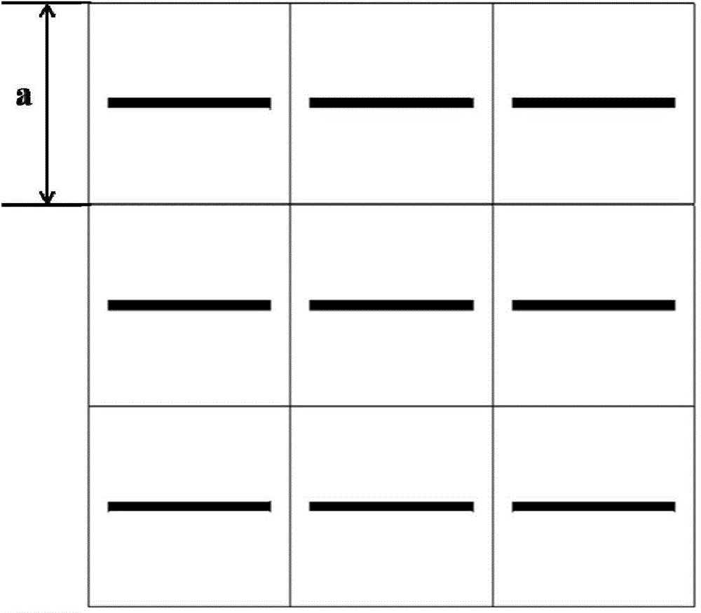
[0026] An electromagnetic wave absorbing structure in which periodic metal copper straight wires are embedded in a 2.0mm thick magnetic wave absorbing material. The unit size is: a=5.0mm, t=2.0mm, t 1 =0.8mm, d=0.25mm, l=4.0mm; the range of electromagnetic parameters of magnetic absorbing materials is: the real part of relative permittivity is 7.7~8.4, the imaginary part is 0.1~0.7; the real part of relative permeability is 1.2 ~3.0, the imaginary part is 0.6~1.1.
[0027] In the TE polarization mode, when the periodic metal wire is not loaded, the electromagnetic absorbing structure has better frequency stability, and has better absorbing performance in the angle of incidence range of 0° to 45°; when the loading period is After the metal wire, the oblique incidence performance of the electromagnetic wave absorbing structure has not changed. In the TM polarization mode, when there is no periodic metal wire loaded, the -10dB bandwidth of the electromagnetic absorbing structure at...
Embodiment 2
[0029] In this embodiment, a periodic metal copper straight wire is embedded in a 2.0 mm thick magnetic absorbing material. The unit size is: a=3.0mm, t=2.0mm, t 1 =0.8mm, d=0.25mm, l=2.8mm; the range of electromagnetic parameters of magnetic absorbing materials is: the real part of the relative permittivity is 7.7~8.4, the imaginary part is 0.1~0.7; the real part of the relative permeability is 1.2 ~3.0, the imaginary part is 0.6~1.1.
[0030] In the TE polarization mode, when the periodic metal wire is not loaded, the electromagnetic absorbing structure has better frequency stability, and has better absorbing performance in the angle of incidence range of 0° to 45°; when the loading period is After the metal wire, the oblique incidence performance of the electromagnetic wave absorbing structure has not changed. In the TM polarization mode, when there is no periodic metal wire loaded, the -10dB bandwidth of the electromagnetic absorbing structure at different incident angles is...
Embodiment 3
[0032] An electromagnetic wave absorbing structure is to embed periodic metal copper straight wires in a 1.8mm thick magnetic wave absorbing material. The unit size is: a=4.0mm, t=2.0mm, t 1 =0.8mm, d=0.25mm, l=3.5mm; the range of the electromagnetic parameters of the magnetic plate material is: the real part of the relative permittivity is 7.7~8.4, the imaginary part is 0.1~0.7; the real part of the relative permeability is 1.2~ 3.0, the imaginary part is 0.6 to 1.1.
[0033] In the TE polarization mode, when the periodic metal wire is not loaded, the electromagnetic absorbing structure has better frequency stability, and has better absorbing performance in the angle of incidence range of 0° to 45°; when the loading period is After the metal wire, the oblique incidence performance of the electromagnetic wave absorbing structure has not changed. In the TM polarization mode, when the periodic metal wire is not loaded, the -10dB bandwidth of the electromagnetic absorbing structure...
PUM
 Abstract
Description
Claims
Application Information
 - R&D
- Intellectual Property
- Life Sciences
- Materials
- Tech Scout
- Unparalleled Data Quality
- Higher Quality Content
- 60% Fewer Hallucinations
Browse by: Latest US Patents, China's latest patents, Technical Efficacy Thesaurus, Application Domain, Technology Topic, Popular Technical Reports.
© 2025 PatSnap. All rights reserved.Legal|Privacy policy|Modern Slavery Act Transparency Statement|Sitemap|About US| Contact US: help@patsnap.com


