Pump radiation arrangement and method for pumping a laser-active medium

A technology of radiation device and laser activity, applied in the structure/shape of active medium, active medium material, laser, etc., can solve the problems of increasing laser output power, undesired widening of spectrum, and reducing the efficiency of pump radiation device, etc.

Active Publication Date: 2015-01-28
TRUMPF LASER GMBH CO KG
View PDF11 Cites 3 Cited by
  • Summary
  • Abstract
  • Description
  • Claims
  • Application Information

AI Technical Summary

Problems solved by technology

[0005] However, despite reflectors that reflect wavelengths in a narrow band, the wavelength-stabilized pump radiation transmitted from the reflector usually also has a spectral part in the wavelength range that is not absorbed or is only weakly absorbed by the laser-active medium.
Undesired spectral parts are reflected by the end mirror back to the pump radiation source, especially when the pump radiation device is operated at high radiation powers, mainly when, for example, in tertiary or quasi-tertiary laser media due to laser The increased inversion of the medium weakens the absorption (ausbleichen), which occurs especially in so-called zero-phonon-absorption lines (Zero-Phonon-Absorptionslinie) (e.g. 969 nm in the case of Yb:YAG, or in the case of Yb:Lu 2 o 3 In the case of 976 nanometers), however, the following problem arises: the undesired reflected back part of the spectrum leads to destabilization of the pump radiation source, so that the transmitted spectrum of the pump radiation from the reflector is undesirably broadened
Despite reflectors, the deviation of the pump radiation spectrum from the absorption spectrum of the laser-active medium reduces the efficiency of the pump radiation device, so that the output power of the laser or amplifier cannot be increased as desired

Method used


Image

  • Pump radiation arrangement and method for pumping a laser-active medium
  • Pump radiation arrangement and method for pumping a laser-active medium
  • Pump radiation arrangement and method for pumping a laser-active medium

Examples


Embodiment Construction

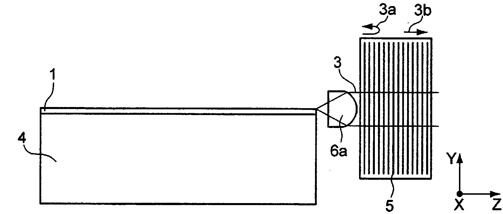
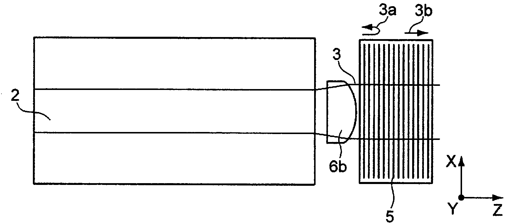
[0046] Figure 1a , b strongly schematically shows the pump radiation source 1 in side view or top view. The pump radiation source 1 is concerned in this example for generating radiation at, for example, 969 nm (for pumping Yb:YAG as the laser active medium) or for example 976 nm (for pumping Yb:Lu as the laser active medium) 2 o 3 ) target wavelength λ z at the pump radiation of the laser diode. The pump radiation source 1 has an active region 2 in which photons or pump radiation 3 are generated when the pump radiation source 1 is energized with a current density exceeding a threshold current density. In this example, the active area 2 is composed of Indium Gallium Arsenide (InGaAs), but it is understood that other semiconductor materials may also be used. The pump radiation source 1 is applied to the heat sink 4 and emits pump radiation 3 which extends in the Z direction of the XYZ coordinate system.

[0047] The pump radiation 3 emerges divergently from the pump radiati...


PUM


Abstract

The invention relates to a pump radiation arrangement (11), comprising: a pump radiation source (1) for creating pump radiation (3), a medium (5) for stabilising the wavelengths of the pump radiation source (1), and a laser-active medium (12), through which the pump radiation (3) runs bidirectionally. The pump radiation arrangement (11) also has a retroreflector (14) for reflecting the pump radiation (3c) not absorbed by the laser-active medium (12) back to the pump radiation source (1), and a wavelength-selective element (15) for avoiding wavelength destabilisation of the pump radiation source (1) by filtering undesired spectral components (10) of the pump radiation (3c) not absorbed by the laser-active medium (12). For example, a laser diode with an external volume Bragg grating can be used for pumping, wherein a coupled resonator of the LD has a Yb:YAG as a laser-active medium, as well as a Fabry-Perot etalon for suppressing spectral components that are not suppressed by the narrow-band VBG.

Description

technical field [0001] The invention relates to a pump radiation arrangement comprising a pump radiation source for generating pump radiation and means for wavelength stabilization of the pump radiation source, for example in the form of a grating structure. The invention also relates to a method for pumping a laser-active medium, comprising the steps of generating pump radiation by means of a pump radiation source, stabilizing the wavelength of the pump radiation, for example by means of a grating structure, and pumping a laser by means of the pump radiation active medium. Background technique [0002] A radiation source for high radiation powers is known from WO 2006 / 025849 A2, which comprises a semiconductor diode laser as pump radiation source and a reflector with a grating structure. The reflector is optically connected to the semiconductor diode laser and is aligned with the output beam of the diode laser in such a way that a portion of the radiation in the output bea...

Claims


Application Information

Patent Timeline
IPC IPC(8): H01S3/094H01S3/0941H01S5/065H01S5/14H01S3/1055H01S3/106H01S3/16H01S3/06
CPCH01S3/09415H01S5/0654H01S3/1062H01S5/0656H01S5/142H01S3/1618H01S3/1055H01S3/0604H01S3/094084H01S3/1643H01S5/146H01S3/094015H01S3/091
Inventor D·祖特尔A·基利J·克莱因鲍尔Y·李
Owner TRUMPF LASER GMBH CO KG
Why Eureka
Try Eureka