Ball screw support device

A support device and ball screw technology, applied in feeding devices, metal processing mechanical parts, metal processing equipment, etc., can solve the problems affecting the dynamic running stability of the whole machine, the movement accuracy error of the feed axis, affecting the stability of the worktable, etc. problem, to achieve the effect of simple and reliable structure, reduced deflection and deformation, and low cost

Inactive Publication Date: 2015-02-04
南京金宇刀具制造有限公司
View PDF0 Cites 7 Cited by
  • Summary
  • Abstract
  • Description
  • Claims
  • Application Information

AI Technical Summary

Problems solved by technology

But when the stroke of the workbench is large, because the lead screw is too long, the hanging part in the middle will cause the deflection and deformation of the lead screw due to its own weight, causing the middle part of the ball screw to bend downward, which will affect the stability of the worktable movement , which will cause errors in the movement accuracy of the feed axis, resulting in errors in the machining accuracy of the workpiece, and will also affect the stability of the dynamic operation of the whole machine

Method used


Image

  • Ball screw support device
  • Ball screw support device
  • Ball screw support device

Examples


Embodiment Construction

[0012] A ball screw support device proposed by the present invention will be described in detail below with reference to the accompanying drawings.

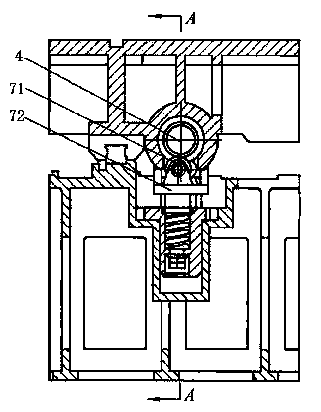
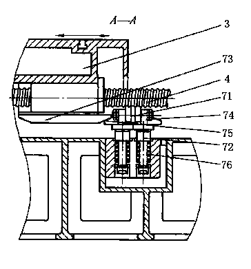
[0013] Such as figure 1 with 2 As shown, a ball screw supporting device disclosed in the present invention includes a support rod 72, a spring 76, a roller 71, an upper inclined plate 73 and a lower inclined plate 75; the spring 76 is sleeved on the support rod 72, and the support rod 72 has Boss, spring 76 is located below the boss. The upper sloping plate 73 is installed on the external workbench 3 , and the lower sloping plate 75 is installed on the support rod 72 . The roller 71 is installed on the top of the support rod 72 , and the shaft of the roller 71 is fixedly connected with the top of the support rod 72 by a screw 74 . There are two supporting rods 72, springs 76, and rollers 71, which are arranged symmetrically.

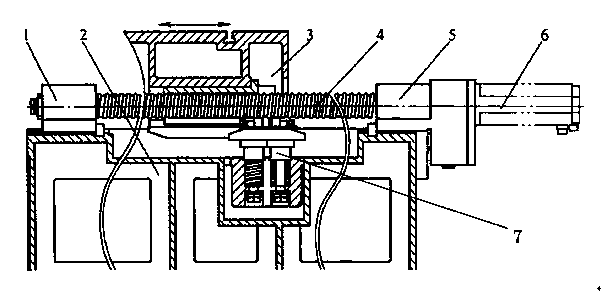
[0014] Such as image 3 As shown, install the ball screw support device 7 on the machine tool. The...


PUM


Abstract

The invention discloses a ball screw support device. The ball screw support device comprises a support rod (72), a spring (76), an idler wheel (71), an upper inclined plate (73) and a lower inclined plate (75), wherein the spring (76) sleeves the support rod (72); the upper inclined plate (73) is arranged on an external workbench (3); the lower inclined plate (75) is arranged on the support rod (72); the idler wheel (71) is arranged on the top end of the support rod (72). According to the ball screw support device, the ball screw bending is reduced, the deflection deformation is reduced, and thus the movement precision of the workbench is guaranteed; the precision and the rigidity of a machine tool are improved. The ball screw support device is simple and reliable in structure, good in maintainability and low in cost.

Description

technical field [0001] The invention belongs to the technical field of mechanical equipment, in particular the invention discloses a ball screw support device. Background technique [0002] The roller screw is generally composed of a screw, a nut, a steel ball, a preloader, a reverser, and a dust collector. Its function is to convert rotary motion into linear motion, which is widely used in equipment such as machine tools, such as the mobile workbench of machine tools. In the column fixed table mobile gantry milling machine, the table movement is driven by the servo motor through the ball screw, and the two ends of the ball screw are supported by the bearing housing. But when the workbench stroke is large, because the lead screw is too long, the hanging part in the middle will cause the deflection and deformation of the lead screw due to its own weight, causing the middle part of the ball screw to bend downward, thus affecting the stability of the worktable movement , thus...

Claims


Application Information

Patent Timeline
Patent Type & Authority Applications(China)
IPC IPC(8): B23Q5/40
CPCB23Q5/404
Inventor 陈家林
Owner 南京金宇刀具制造有限公司
Why Eureka
Try Eureka