Air-floating shaft rotating soft abrasive flow polishing device

A technology of polishing device and air bearing shaft, which is applied to the processing device of used abrasives, abrasives, abrasive jet machine tools, etc., can solve the problems of increasing processing costs, high requirements for fluid inlet speed, and long polishing time of workpieces, etc. Achieve the effect of less scratches, fully controllable processing effect and low contact pressure

Active Publication Date: 2017-01-04
ZHEJIANG UNIV OF TECH
View PDF7 Cites 1 Cited by
  • Summary
  • Abstract
  • Description
  • Claims
  • Application Information

AI Technical Summary

Problems solved by technology

In order to achieve a turbulent state for the abrasive particle flow, the fluid in the flow channel must have a high velocity. The existing speed-increasing method mainly introduces a confinement module, which forms a closed confinement channel with the processed wall to make the fluid flow from a narrow However, this method still requires high speed at the fluid inlet port, which puts high demands on the water pump, greatly increases the processing cost, and takes a long time to polish the workpiece. , the polishing efficiency is generally low

Method used


Image

  • Air-floating shaft rotating soft abrasive flow polishing device
  • Air-floating shaft rotating soft abrasive flow polishing device
  • Air-floating shaft rotating soft abrasive flow polishing device

Examples


Embodiment Construction

[0027] In order to make the object, technical solution and advantages of the present invention clearer, the present invention will be further described in detail below in combination with specific embodiments and with reference to the accompanying drawings. It should be understood that these descriptions are exemplary only, and are not intended to limit the scope of the present invention. Also, in the following description, descriptions of well-known structures and techniques are omitted to avoid unnecessarily obscuring the concept of the present invention.

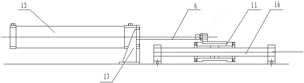
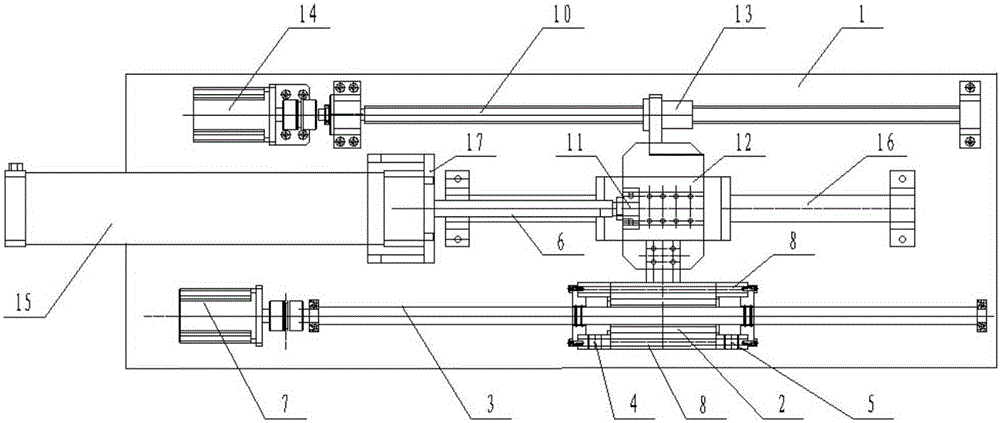
[0028] figure 1 It is the top view of the air bearing rotating soft abrasive flow polishing device; figure 2 It is the principle diagram of slender shaft abrasive flow machining; image 3 is a sectional view of the workpiece clamping device; Figure 4 is the front view of the cushioning device.

[0029] Refer to attached figure 1 with Figure 4 , the air bearing shaft rotating soft abrasive flow polishing device is...


PUM


Abstract

The invention discloses an air-floating shaft rotating soft abrasive flow polishing device, which is used for grinding a slender rod to be processed, comprising a fixed plate, a core polishing device for a slender rod, a workpiece feeding device and a buffer device; the slender The rod core polishing device, the workpiece feeding device, and the buffer device are all fixedly installed on the fixed plate; the workpiece feeding device is used for axial feeding of the slender rod core polishing device, and the buffer device is used for buffering the slender rod core polishing device Axial feed; the slender rod core polishing device includes an internal screw type constraint module, a constraint module mounting seat, a sealing cover, a clamping end cover, an O-ring and a screw rod, and the slender rod to be processed passes through one end of the constraint module mounting seat It is connected with the servo motor through a coupling, and the other end is matched with a rolling bearing. The inside of the constraining module mounting seat forms a constrained flow channel through a sealing cover and a clamping end cover. The invention has high polishing efficiency and good polishing effect, and is extremely suitable for ultra-precision machining of the inner wall.

Description

technical field [0001] The invention relates to the field of soft abrasive flow processing, in particular to an abrasive flow polishing device for polishing a slender shaft. Background technique [0002] With the rapid development of aerospace, medicine, food, chemical and other fields, the demand for various types of pipes at home and abroad is also increasing, and the requirements for the inner wall are becoming more and more stringent. Among them, magnetic polishing, honing, extrusion honing, flexible abrasive body vibration polishing, and small grinding head polishing are common, but there are certain processing limitations for workpieces that require high shape accuracy. For example, extrusion honing and flexible grinding body vibration polishing, because the elastic basic medium with high viscosity is used, it will be subjected to strong shearing action of strong viscous force during wall surface processing, which will destroy the thin wall surface, and at the same tim...

Claims


Application Information

Patent Timeline
Patent Type & Authority Patents(China)
IPC IPC(8): B24C3/32B24C9/00
Inventor 袁巧玲张利单晓杭孙建辉宋卫
Owner ZHEJIANG UNIV OF TECH
Why Eureka
Try Eureka