High-effect electrostatic protective component of disk type voltage dependent resistor for bridge-wire electric detonator
A technology of electrostatic protection devices and piezoresistors, which is applied in the direction of weapon accessories, fuzes, offensive equipment, etc., and can solve the problems of no protection effect, open circuit of the protection circuit, and electrode shedding, etc.
- Summary
- Abstract
- Description
- Claims
- Application Information
AI Technical Summary
Problems solved by technology
Method used
Image


Examples
Embodiment Construction
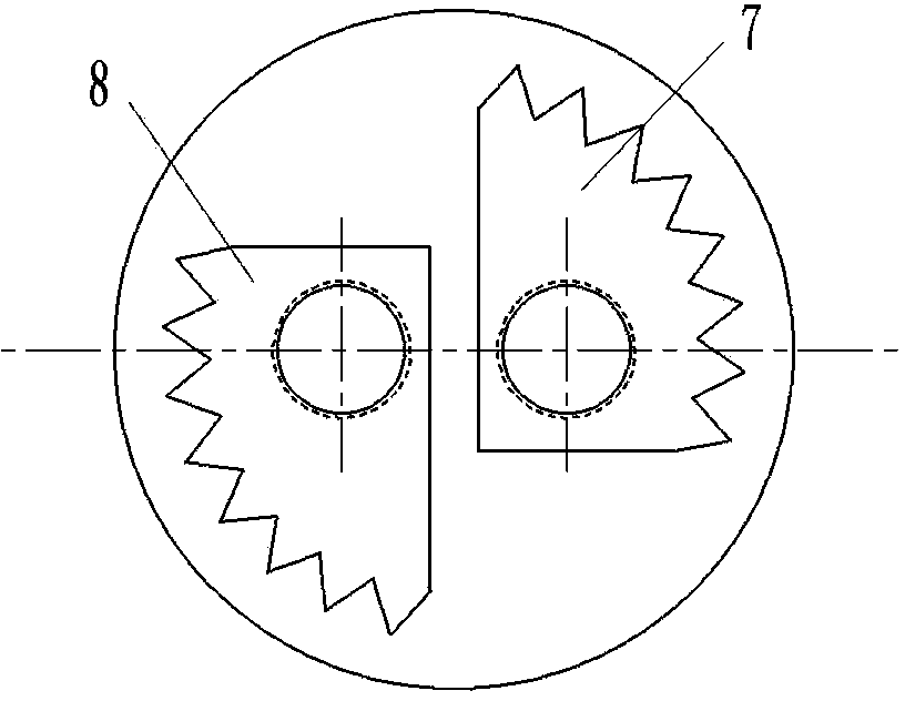
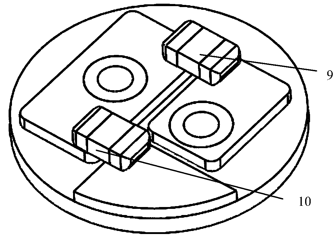
[0024] combine figure 1 , figure 2 , image 3 , The anti-static sheet includes a PCB disc 1 with two holes, three metal pads 2, 5, 6, two metallized via holes 2, 3 and two sawtooth copper clad boards 7, 8, with two Two metallized via holes 2 and 3 are formed after the two holes of the PCB board 1 with two holes are metallized. Metallized via 2 is connected to a rectangular metal pad 4 with a chamfer centered on the center of the hole; another metallized via 3 is connected to another short rectangular metal pad 5; under this short pad 5 there is a The arc-shaped pads 6 with the same edges of the PCB circular plate; two arc-shaped copper clad plates 7, 8 with multiple sawtooths connected to the two metallized via holes 2, 3 under the PCB. Two rectangular metal pads 4 and 5 are welded to the two poles of the protective pin-foot varistor 9, and the long rectangular pad 4 and the arc-shaped metal pad 6 are welded to the two poles of the protective pin-shell varistor 10, thereby...
PUM
| Property | Measurement | Unit |
|---|---|---|
| Diameter | aaaaa | aaaaa |
| Thickness | aaaaa | aaaaa |
| Thickness | aaaaa | aaaaa |
Abstract
Description
Claims
Application Information
 - R&D
- Intellectual Property
- Life Sciences
- Materials
- Tech Scout
- Unparalleled Data Quality
- Higher Quality Content
- 60% Fewer Hallucinations
Browse by: Latest US Patents, China's latest patents, Technical Efficacy Thesaurus, Application Domain, Technology Topic, Popular Technical Reports.
© 2025 PatSnap. All rights reserved.Legal|Privacy policy|Modern Slavery Act Transparency Statement|Sitemap|About US| Contact US: help@patsnap.com