Line interphase fault single-ended distance measurement method based on interphase fault location factor

A technology of inter-phase fault and single-ended ranging, which is applied in the fault location and other directions, and can solve the problems of inability to locate single-ended faults, high sampling rate requirements, and inability to meet application requirements.

Active Publication Date: 2015-02-04
STATE GRID CORP OF CHINA +2
View PDF8 Cites 6 Cited by
  • Summary
  • Abstract
  • Description
  • Claims
  • Application Information

AI Technical Summary

Problems solved by technology

The traveling wave method utilizes the transmission properties of fault transient traveling waves to perform single-ended fault location. It has high precision and is not affected by the operation mode and excessive resistance. However, it requires a high sampling rate, requires a special wave recording device, and has high application costs.
The impedance method uses the voltage and current after the fault to calculate the fault loop impedance, and performs single-ended fault distance measurement according to the characteristic that the line length is proportional to the impedance. It is simple and reliable, but the distance measurement accuracy is seriously affected by factors such as transition resistance and load current, especially When the transition resistance is large, the ranging result of the impedance method will seriously deviate from the real fault distance, and even the ranging failure will occur.
Due to the large distributed capacitive current along the UHV transmission line, when a medium-to-high-resistance short-circuit fault occurs on the UHV transmission line, the ranging result of the single-ended impedance method will seriously deviate from the real fault distance, which cannot meet the application requirements of the site
Therefore, the single-ended impedance method using lumped parameter modeling cannot be directly applied to the single-ended fault location of UHV transmission lines

Method used


Image

  • Line interphase fault single-ended distance measurement method based on interphase fault location factor
  • Line interphase fault single-ended distance measurement method based on interphase fault location factor
  • Line interphase fault single-ended distance measurement method based on interphase fault location factor

Examples


Embodiment Construction

[0017] The technical solution of the present invention will be further described in detail according to the accompanying drawings.

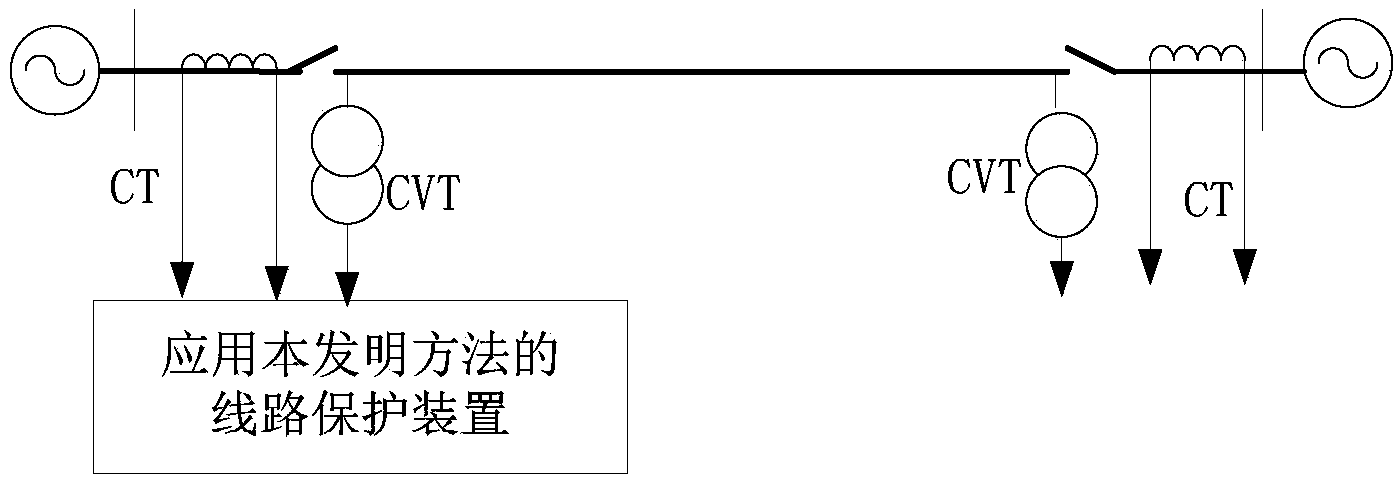
[0018] figure 1 It is a schematic diagram of the line transmission system applying the present invention. figure 1 CVT is a voltage transformer, and CT is a current transformer. The protection device samples the voltage of the voltage transformer CVT and the current waveform of the current transformer CT at the place where the transmission line protection is installed to obtain instantaneous values ​​of voltage and current.

[0019] The protection device uses the Fourier algorithm to calculate the fault phase-to-phase voltage at the protection installation of the transmission line on the sampled voltage and current instantaneous values Fault phase current and negative sequence current between fault phases Among them, φφ=AB, BC, CA phase.

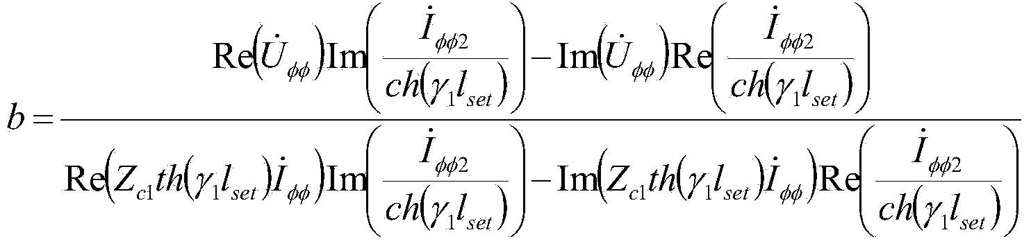
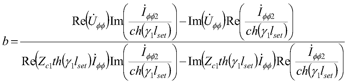
[0020] Protection device calculation¶ 1 l set The hyperbolic cosine function value ch(γ 1 l set ...


PUM


Abstract

The invention discloses a line interphase fault single-ended distance measurement method based on an interphase fault location factor. The method includes firstly, calculating the ratio of fault impedance, from an electric transmission line protection mounting position to an interphase short-circuit fault point, to line impedance, from the electric transmission line protection mounting position to an electric transmission line protection setting range, to acquire the electric transmission line interphase fault location factor b; selecting a fault location default value as lfault, and sequentially calculating the absolute values of [Zc1th(gamma1lfault) / Zc1th(gamma1lset)]-b of points on an electric transmission line by means of progressive increase of a fixed step length delta l until the total length of the electric transmission line is calculated; selecting the distance between the point with the maximum absolute value of [Zc1th(gamma1lfault) / Zc1th(gamma1lset)]-b on the electric transmission line and the electric transmission line protection mounting position as the fault distance. The method has the advantages that influences of electric transmission line interphase short-circuit fault point voltage, transition resistance and load current on electric transmission line interphase short-circuit fault single-ended distance measurement accuracy are eliminated theoretically, and the method has high distance measurement accuracy and is particularly applicable to interphase short-circuit fault single-ended distance measurement of extra-high-voltage alternating-current electric transmission lines.

Description

technical field [0001] The invention relates to the technical field of electric power system relay protection, in particular to a single-end ranging method for line interphase faults based on interphase fault location factors. Background technique [0002] According to the division of electrical quantity sources, fault location methods are mainly divided into double-ended location methods and single-ended location methods. The double-terminal ranging method uses the electrical quantities at both ends of the transmission line to locate faults. It needs to obtain the electrical quantities at the opposite end through the data transmission channel, which is highly dependent on the data transmission channel. UHV AC transmission lines are often long-distance transmission lines, and the laying of data transmission channels required for distance measurement requires a large amount of additional investment. Therefore, the single-end distance measurement method is more practical than ...

Claims


Application Information

Patent Timeline
Patent Type & Authority Applications(China)
IPC IPC(8): G01R31/08
Inventor 曾惠敏
Owner STATE GRID CORP OF CHINA
Why Eureka
Try Eureka