Front-side-illuminating LED light strip test device and method

A technology of LED light strips and LED lights, which is applied in the direction of lamp testing, optical performance testing, single semiconductor device testing, etc., and can solve problems such as large damage to human eyes, inability to use industrial field production tests, and poor resolution

Active Publication Date: 2015-02-04
苏州威盛视信息科技有限公司
View PDF7 Cites 11 Cited by
  • Summary
  • Abstract
  • Description
  • Claims
  • Application Information

AI Technical Summary

Problems solved by technology

[0002] The LED light bar test is generally manually plugged in and then visually observed the LED lights on and off, bright and dark, color shift and other issues, the detection speed is slow and the resolution is poor, and the bright LED lights are harmful to human eyes. Large, for the automatic test method, the industry generally adopts the mechanical one-by-one test method. Although the precision is high, the test speed is slower than the manual test, and it cannot be used for production test on the industrial site

Method used


Image

  • Front-side-illuminating LED light strip test device and method
  • Front-side-illuminating LED light strip test device and method
  • Front-side-illuminating LED light strip test device and method

Examples


Embodiment 1

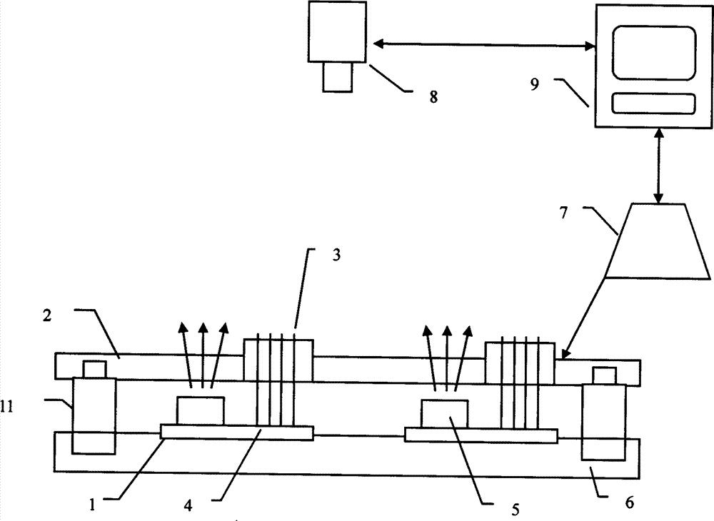
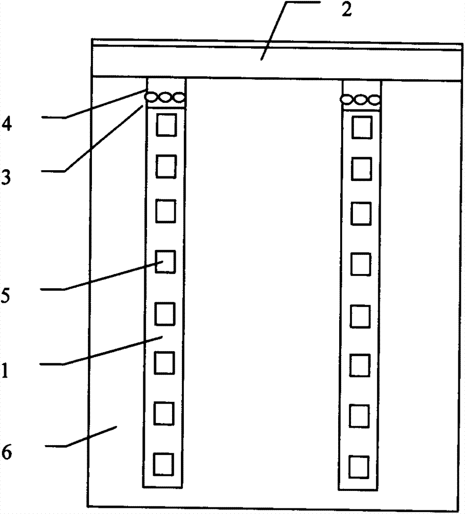
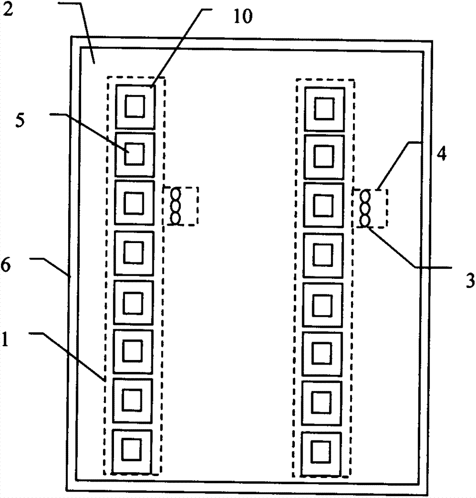
[0036] Embodiment one: if figure 1 As shown, the positive-emitting positive-emitting LED light bar test device includes a light bar 1, a light bar carrier 6, a light bar power module 7, a light bar test board 2, a digital camera 8, and a calculation control unit 9. The light bar 1 There are a plurality of LED lights 5 on it, and there are multiple light bars 1. The light bar 1 is fixed on the light bar carrier 6, and the light bar power module 7 indirectly supplies power to the light bar 1 through the light bar test board 2. The light bar board pin 4 of the light bar 1 is connected to the light bar test board 2, the power terminal of the light bar test board 2 is connected to the light bar power module 7, and the control terminal of the light bar power module 7 is connected to the computer control unit 9. Specific implementation methods, such as figure 1 As shown, a PIN pin 3 is fixed on the light bar test board 2 , one end of the PIN pin 3 is tied to the pin 4 of the light ...

Embodiment 2

[0042] Embodiment two: if Figure 5 As shown, the difference from Embodiment 1 is that the light strip test board 2 is an opaque plate, the light transmission device 10 is a first light transmission hole 13, and the first light transmission hole 13 is located on the light strip test board 2 , which is located directly above the LED light 5. In this way, the light of the positively emitting LED lamp 5 can normally pass through the light bar test board 2 and shine on the digital camera 8 for imaging. In addition, the difference from the above-mentioned embodiment is that the pins 4 of the light bar board on the LED light bar 1 are led to the edge of the light bar carrier 6 through the light bar carrier 6, and the light bar power supply module 7 is directly connected to the light bar The light strip board pin 4 on the edge of the strip carrier 6 is connected.

Embodiment 3

[0043] Embodiment three: as Figure 6 As shown, the difference from Embodiment 1 is that the light-transmitting device 10 is a light-guiding device, and the light-guiding device is a first light-guiding post 14, and the first light-guiding post 14 is fixed on the light bar test board 2, which Located directly above the LED lamp 5. like Figure 7 As shown, the upper surface of the first light guide post 14 is an atomized surface, and the atomized surface is the atomized surface 12 after polishing. like Figure 8 As shown, the atomized surface is a layer of atomized film 15 attached to the first light guide post 14 .


PUM


Abstract

The invention relates to a front-side-illuminating LED light strip test device which comprises light strips, a light strip carrier, a light strip power module, a light strip test board, a digital camera and a computing control unit. The light strips are provided with a plurality of LED lights and fixed to the light strip carrier. A plurality of light strips are arranged. The light strip power module supplies power to the LED light strips. The light strip test board is provided with a light-transmitting device and is located above the light strip carrier through a locating device. The digital camera is fixedly arranged above the light strip test board. The light rays of the LED lights on the light strips illuminate the digital camera through the light strip test board. The digital camera is connected with the computing control unit. According to the method, multiple light strips (ten to sixty light strips) can be tested at the same time, and the test speed is increased by 10-60 times compared with that of manual work; and moreover, uncertainty influence of human factors is avoided, and the test specification takes the numerical value as the standard, so that the stability and precision are ensured, and the online test requirement of the LED light strips can be met completely, the cost is saved, the efficiency is improved, and the quality is ensured.

Description

technical field [0001] The invention relates to a test device and method for positively emitting LED light bars. Background technique [0002] The LED light bar test is generally manually plugged in and then visually observed the LED lights on and off, bright and dark, color shift and other issues, the detection speed is slow and the resolution is poor, and the bright LED lights are harmful to human eyes. Large, for the automatic testing method, the industry generally adopts the mechanical one-by-one testing method. Although the accuracy is high, the testing speed is slower than manual testing, and cannot be used for production testing on the industrial site. Contents of the invention [0003] In order to solve the above problems, the present invention provides a test device and method for positively emitting LED light strips. It has no uncertain influence of human factors, ensures stability and accuracy, and can fully meet the online testing requirements of LED light stri...

Claims


Application Information

Patent Timeline
Patent Type & Authority Applications(China)
IPC IPC(8): G01R31/44G01R31/26G01M11/02
Inventor 张智海易永祥李斯文
Owner 苏州威盛视信息科技有限公司
Why Eureka
Try Eureka